3.4 Instrucciones de montaje
- Drill a bore in the machine frame for the rear anchor pin of the flange.
- Set the control spindle to the initial or referring position.
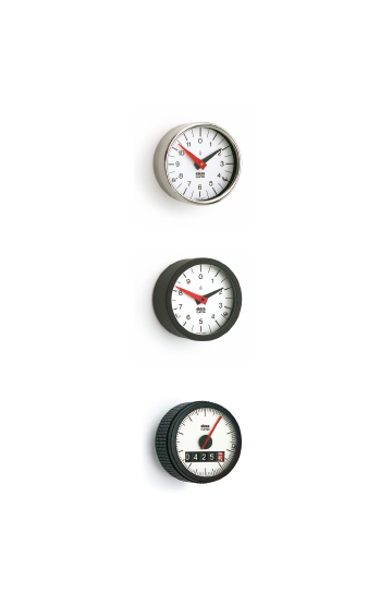
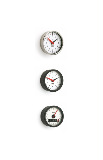
- Remove the black protection cap of the planet pinion, turn the latter until the pointers are in zero position.
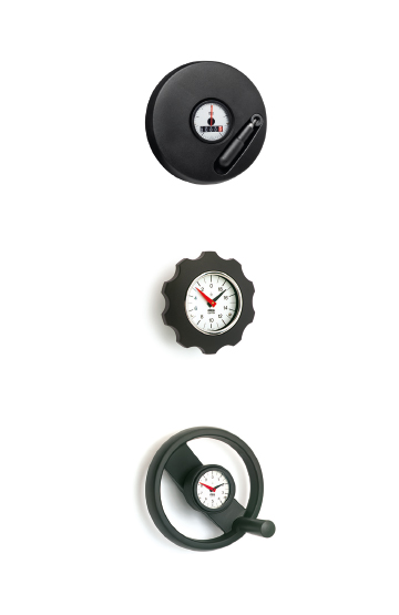
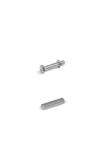
- Take the chosen handwheel/knob and mount the supplied anchor pin on the screw protruding from the rear flange. Be sure that the hole for the indicator planet pinion is at 12 o’clock. Turn the rear flange and position the anchor pin in line with the referring bore drilled on the machine.
- Gently fit the zeroed indicator into the handwheel/knob, inserting the planet pinion smoothly into the corresponding hole. To make the fitting of the indicator easier, gently turn by some degrees the rear flange until the planet pinion is geared to the internal crown gear wheel. Check that the indicator is zeroed and that the screw for the anchor pin is in the correct position.
- Uniformly tighten the lateral grub screws for fixing the indicator case with a moderate torque, to prevent distortion of the case itself and thus locking the movement.
- Adjust the height of the anchor pin so that no undue strain is caused to the flange and tighten the locknut.
- Couple the handwheel with the indicator to the zeroed control spindle. Be sure that the indicator pointers are in zero position and that the anchor pin is in line with the referring bore on the machine. Pin the handwheel on the spindle.
- Check the right functioning of the indicator over all the rotation range.