

SELF-SANITISATION AGAINST BACTERIA AND FUNGI
Close
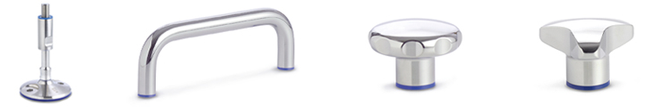
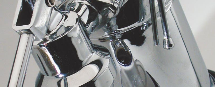
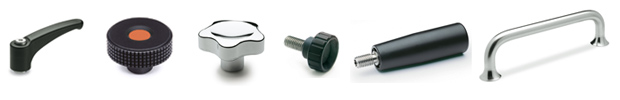
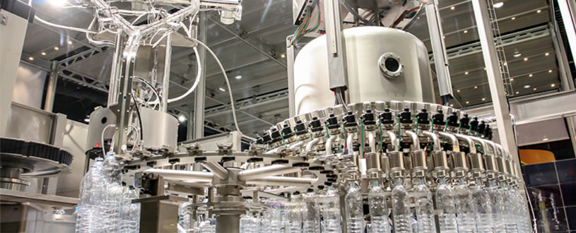
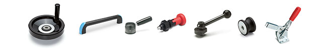
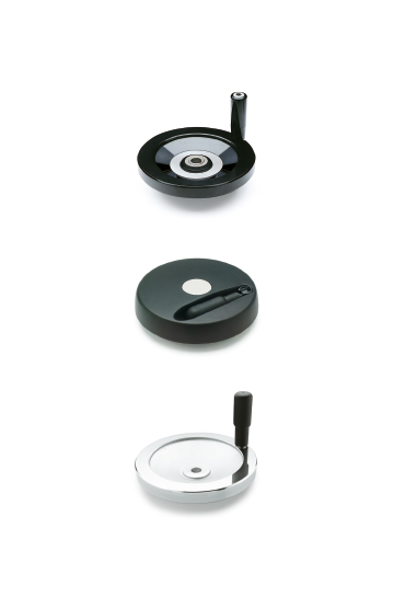
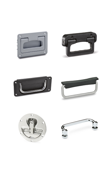
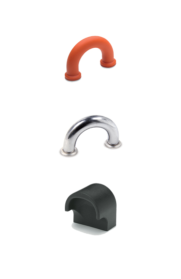
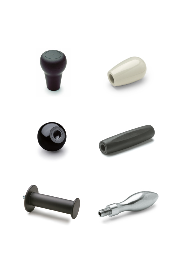
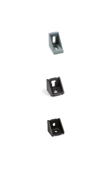
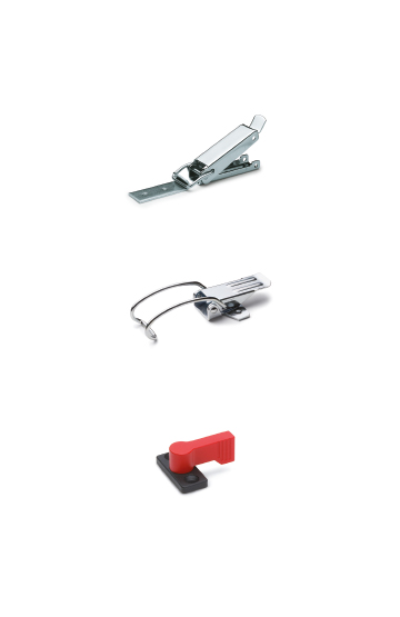
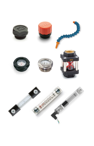
Components for manoeuvring, clamping and locking operations on equipment, including sports equipment and furniture in the nautical sector.
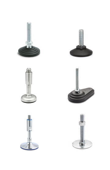
Corrosion resistance, ergonomics, compact shapes and great care in the choice of materials and finishes ease of cleaning
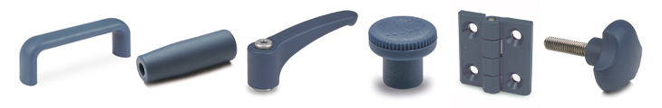
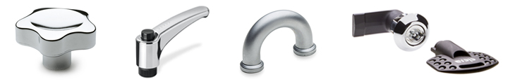
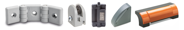
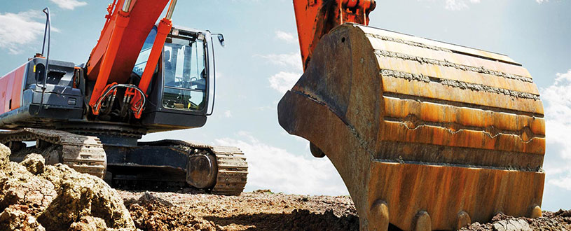
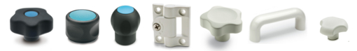
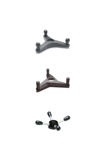
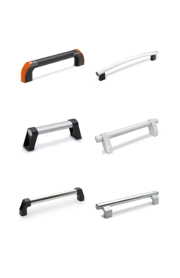
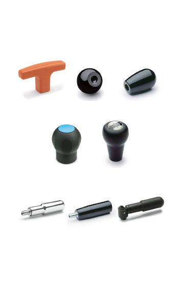
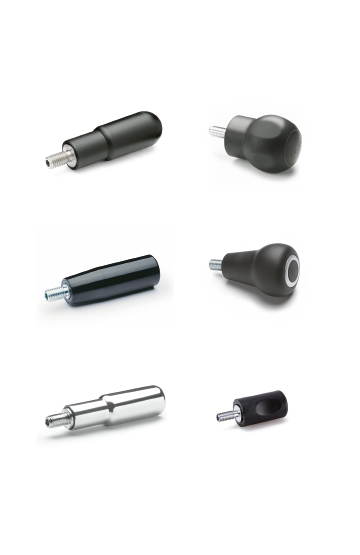
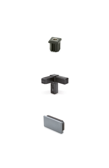
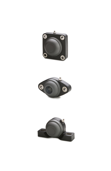
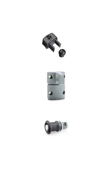
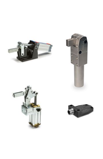
Components for construction vehicles, equipment and machinery which operate in particularly unfavourable conditions
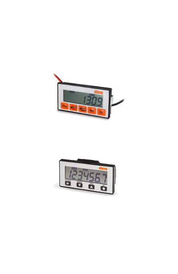
High quality standards, precision in tolerances and care in surface finishes are requirements that ensure greater precision in operation
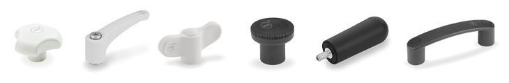
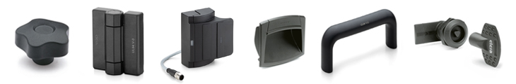
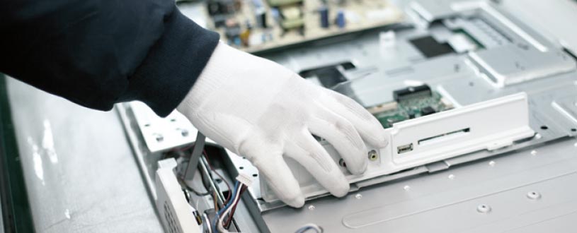
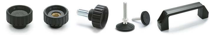
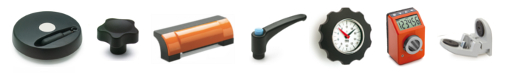
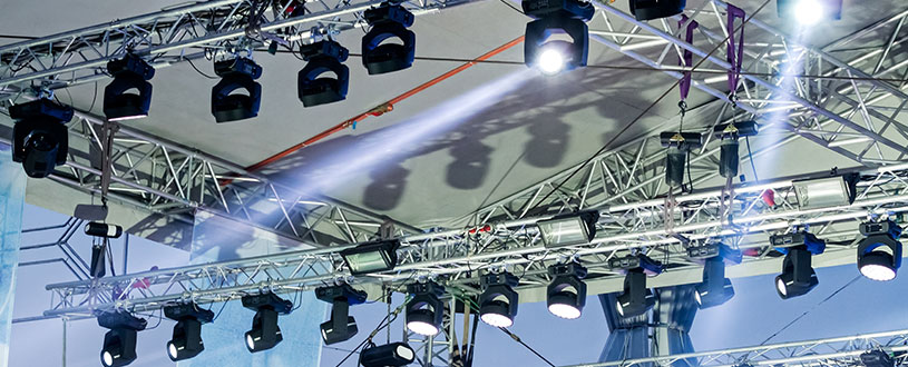
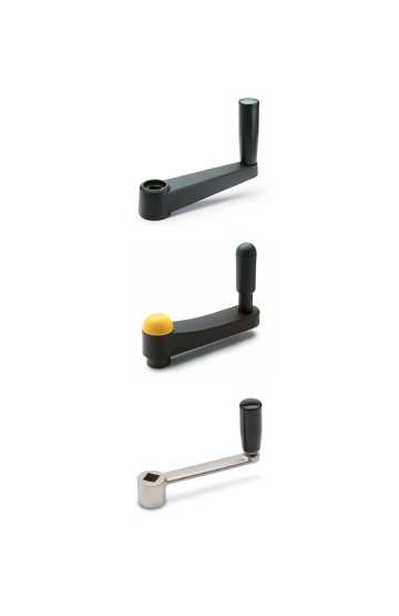
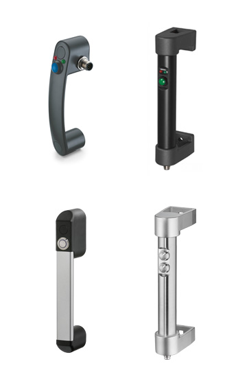
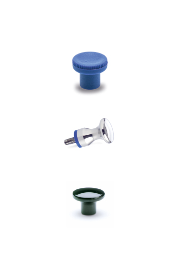
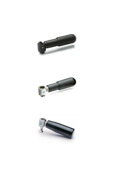
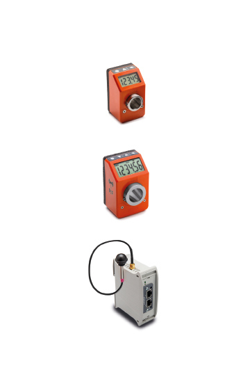
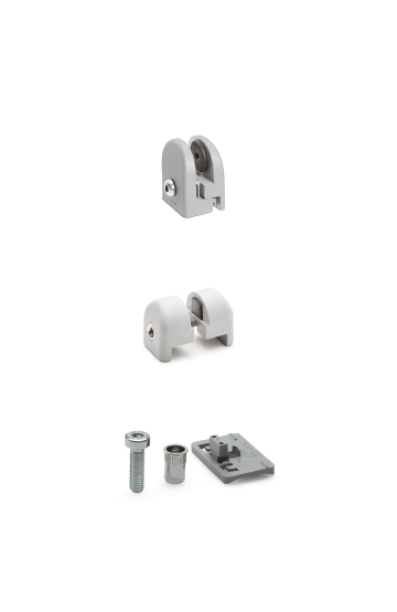
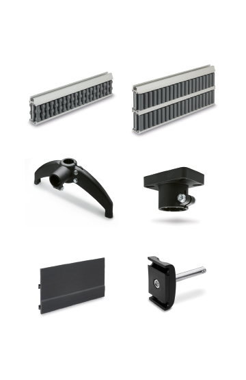
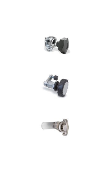
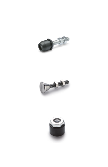
Clamping knobs, adjustable handles and self-locking pins for clamping operations in the field of photography, lighting and electronic equipment
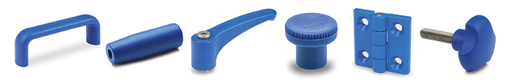
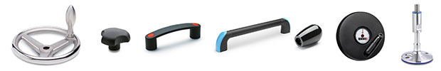
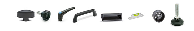
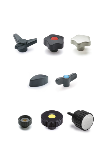
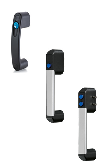
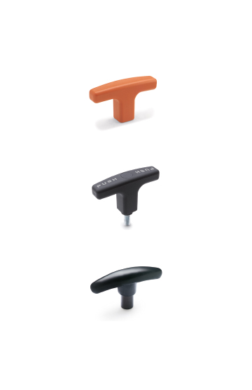
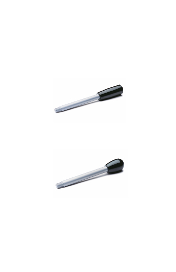
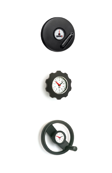
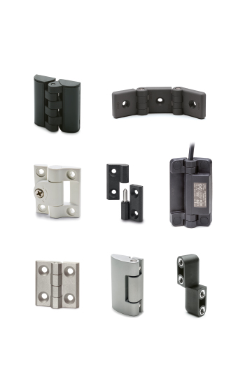
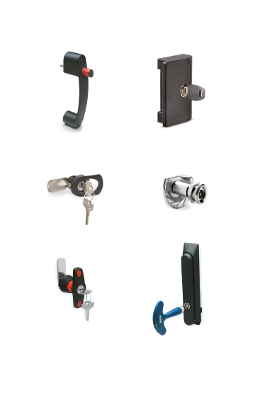
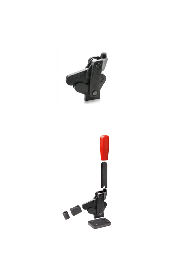
Components to perform clamping and locking operations on machinery or equipment. Ergonomics and design combined with colours
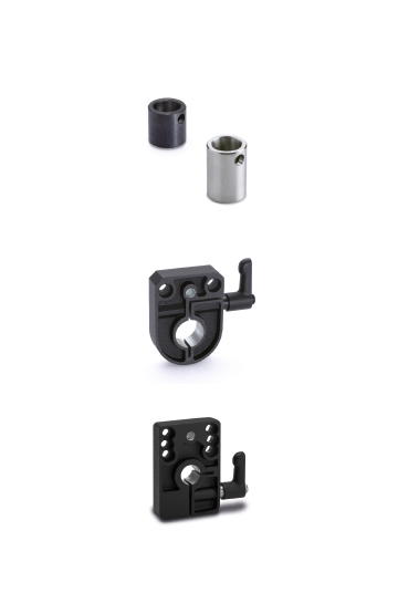
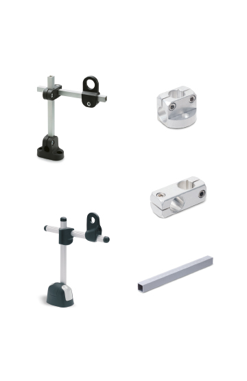
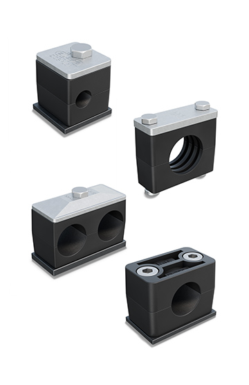
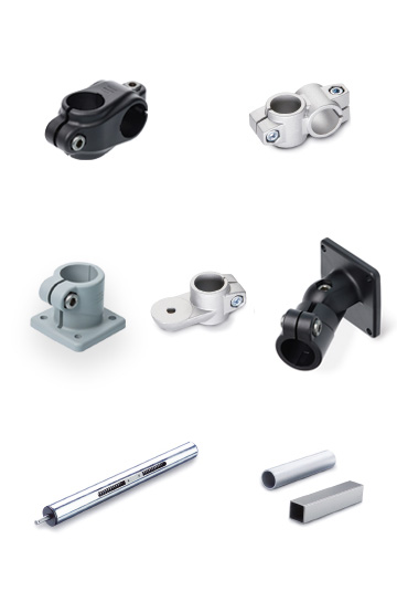
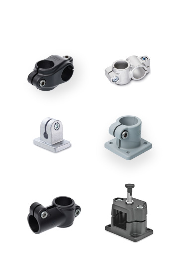
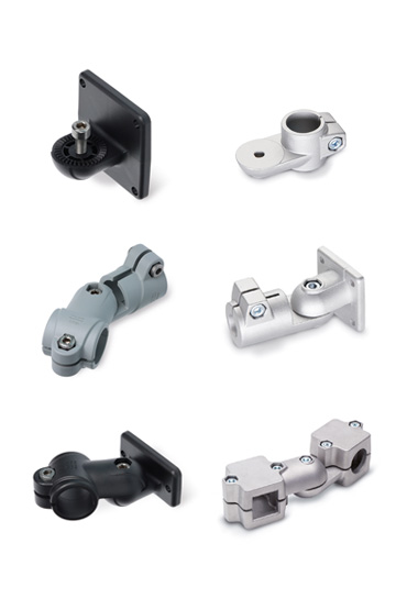
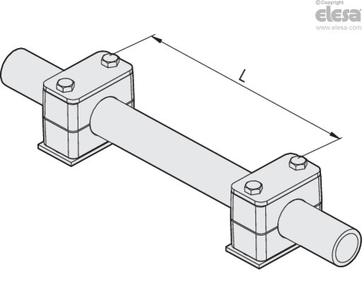
If the section of the tube is straight, a minimum distance between the pairs of tube clamps must be provided; this mainly depends on the tube diameter.
These distances apply to all tube clamp series such as: DCE-S, DCE-H, DCE-D and the corresponding assembled kits DCK-S, DCK-H, DCK-D.
The table shows the recommended minimum distances
| Tube external diameter | L [m] |
|---|---|
| 6 - 13.5 | 1 |
| 13.5 - 18 | 1.2 |
| 18 - 32 | 1.5 |
| 32 - 38 | 2 |
| 38 - 57.2 | 2.7 |
| 57.2 - 75 | 3 |
| 75 - 76.1 | 3.5 |
| 76.1 - 88.9 | 3.7 |
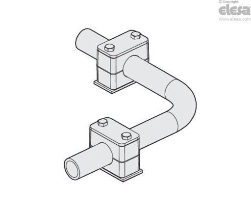
In addition to the linear distance, it is important to ensure that the tube clamps are positioned correctly near sharp curves. Specifically, the tube clamps must be positioned on each side of the curve, as close as possible to the bend.
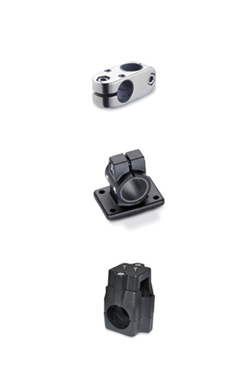
The table shows the values of the tightening torque and axial force F for the mounting of KITs DCK-S, DCK-H and DCK-D respectively.
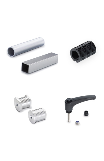
In particular, the KIT configuration allows for the use of tube clamps DCE-S (Standard Series), DCE-H (Heavy-duty Series), DCE-D (Double Series) and with top plates (DCE-PU), lower plates to be welded (DCE-PL) and hexagon head screws (DCE-SRE).
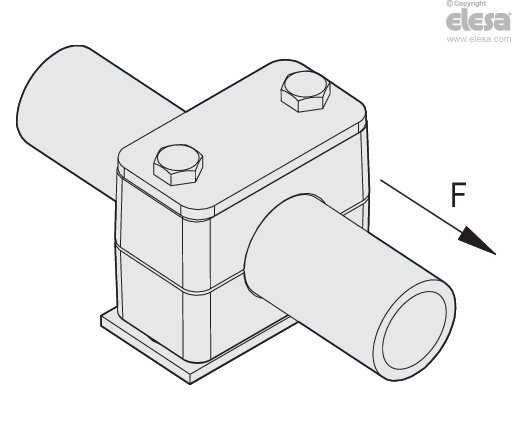
The load value F is an average value from tests carried out with S 235 JR steel tube.
If the tube clamp is subjected to axial stress, the tube will not slip inside the clamp.
Sliding occurs when the F value has been reached.
| Standard series | |||
|---|---|---|---|
| Group | Screw | Tightening torque [Nm] |
Maximum axial load F [kN] |
| 1 | M6 | 8 | 0.7 |
| 2 | M6 | 8 | 1.2 |
| 3 | M6 | 8 | 1.5 |
| 4 | M6 | 8 | 1.7 |
| 5 | M6 | 8 | 1.8 |
| 6 | M6 | 8 | 2 |
| 7 | M6 | 8 | 2.2 |
| Heavy-duty series | |||
|---|---|---|---|
| Group | Screw | Tightening torque [Nm] |
Maximum axial load F [kN] |
| 1 | M10 | 13 | 1.8 |
| 2 | M10 | 13 | 3 |
| 3 | M10 | 15 | 3.5 |
| 4 | M12 | 30 | 8.5 |
| 5 | M16 | 46 | 11.5 |
| Double series | |||
|---|---|---|---|
| Group | Screw | Tightening torque [Nm] |
Maximum axial load F [kN] |
| 1 | M6 | 6 | 1.1 |
| 2 | M8 | 13 | 2.5 |
| 3 | M8 | 13 | 2.1 |
| 4 | M8 | 13 | 2.9 |
| 5 | M8 | 9 | 2.2 |