

SELF-SANITISATION AGAINST BACTERIA AND FUNGI
Close
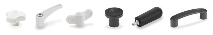
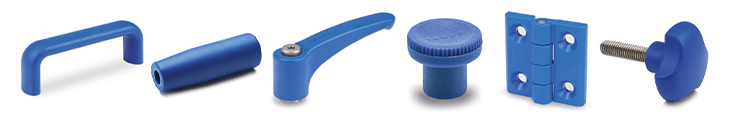
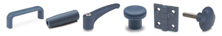
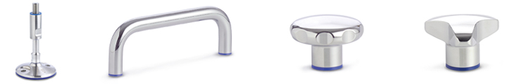
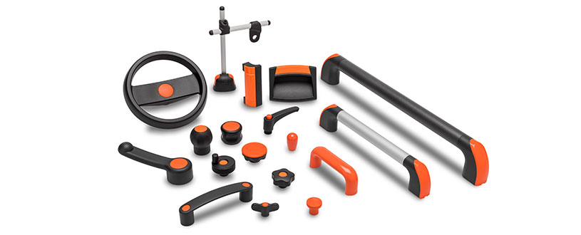
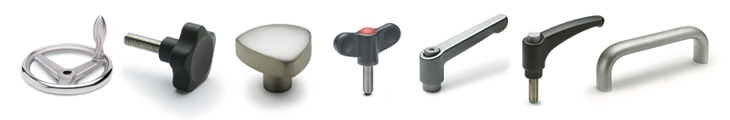
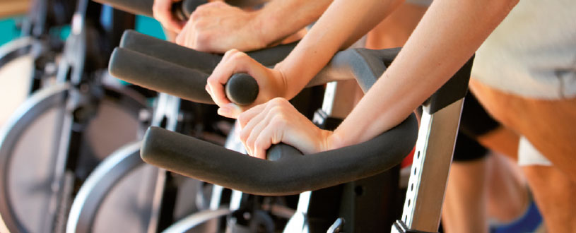
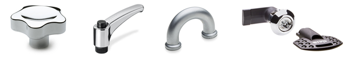
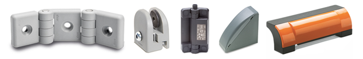
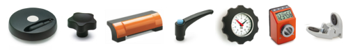
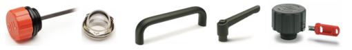
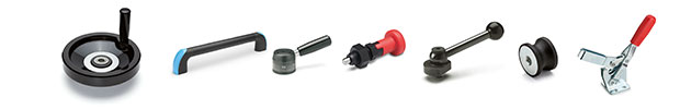
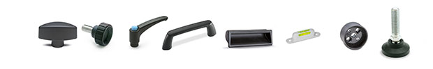
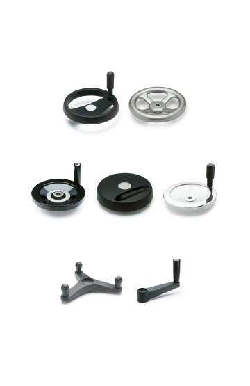
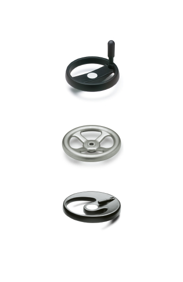
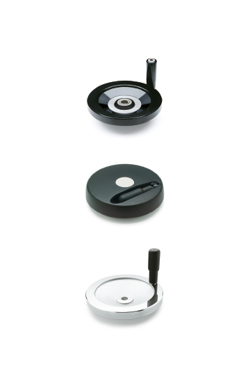
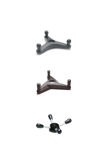
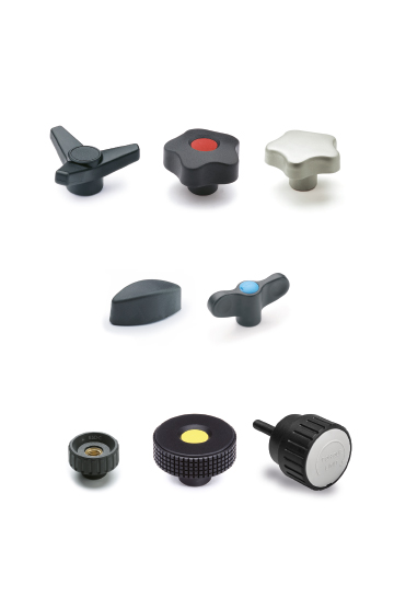
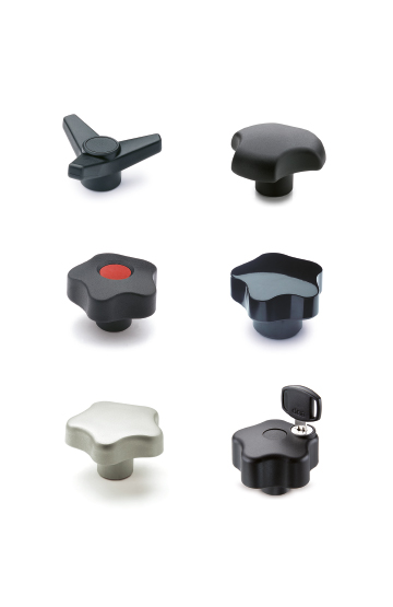
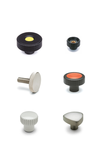
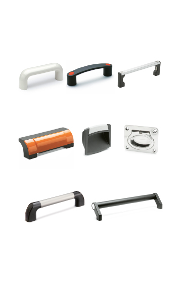
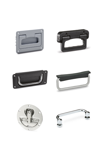
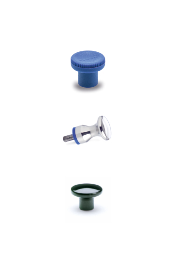
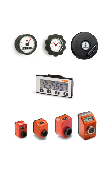
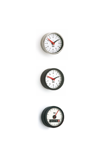
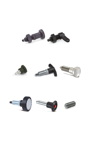
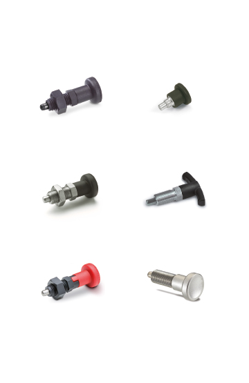
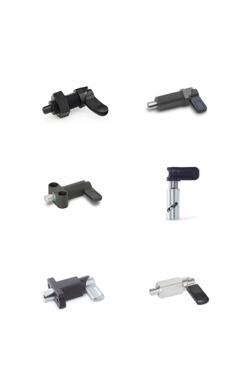
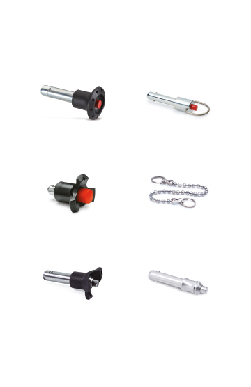
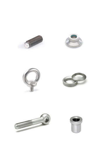
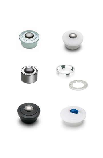
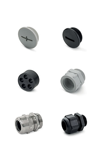
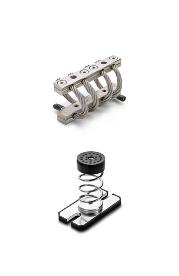
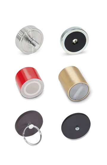
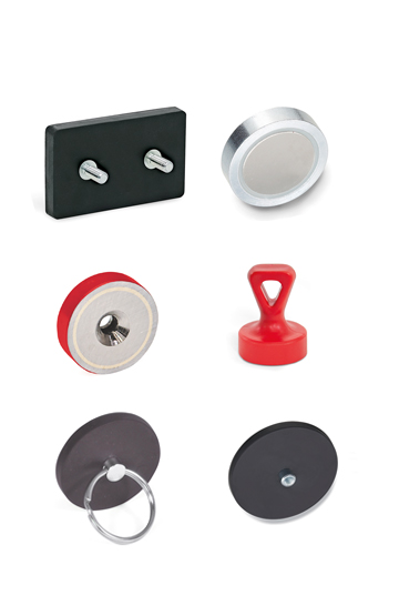
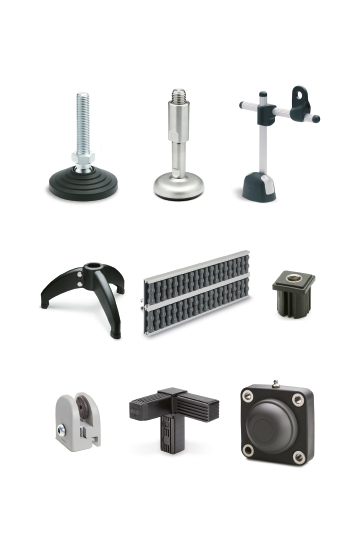
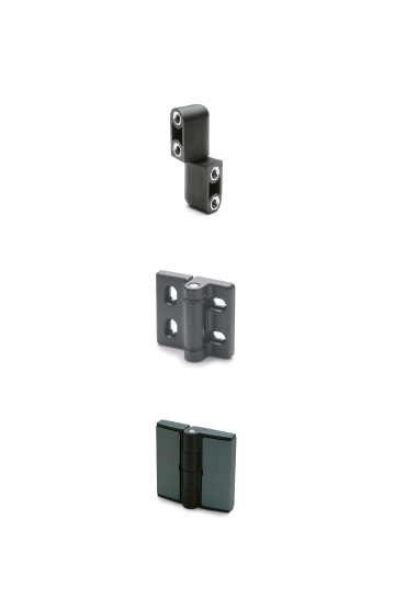
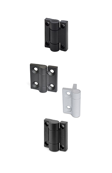
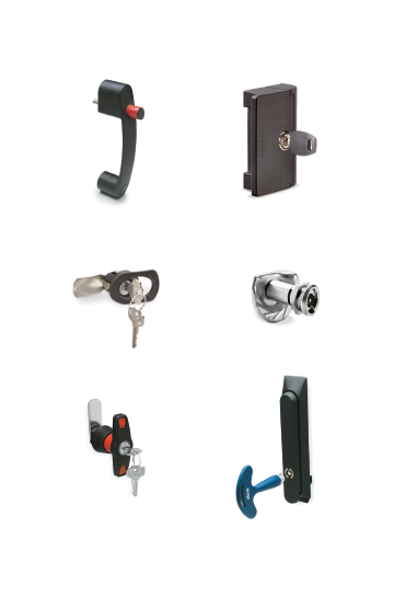
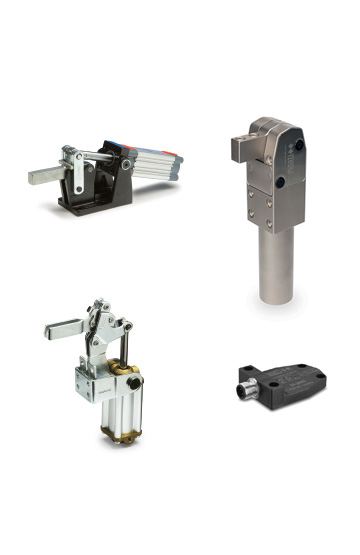
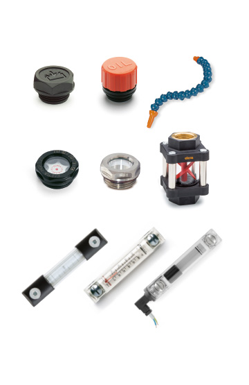
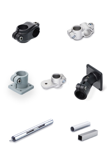
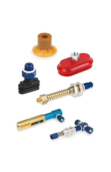
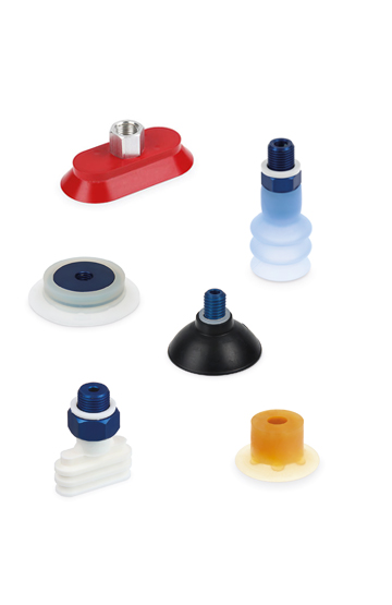
Components for manoeuvring, clamping and locking operations on equipment, including sports equipment and furniture in the nautical sector.
Corrosion resistance, ergonomics, compact shapes and great care in the choice of materials and finishes ease of cleaning
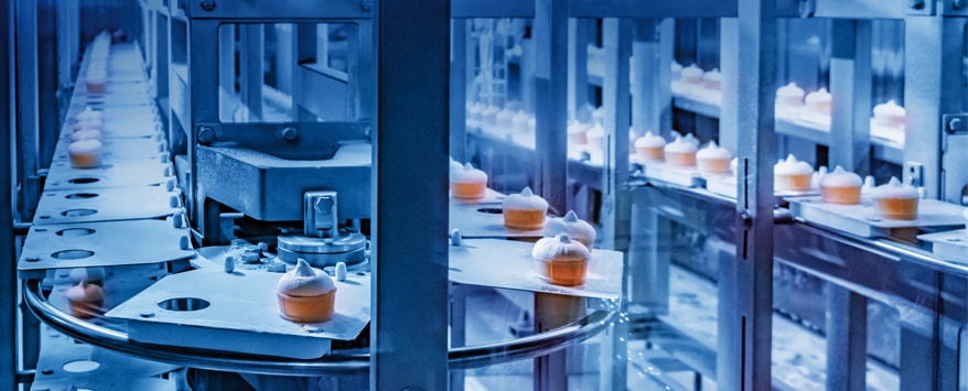
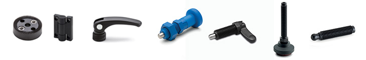
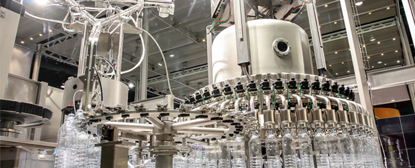
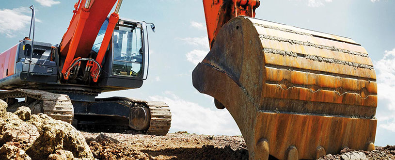
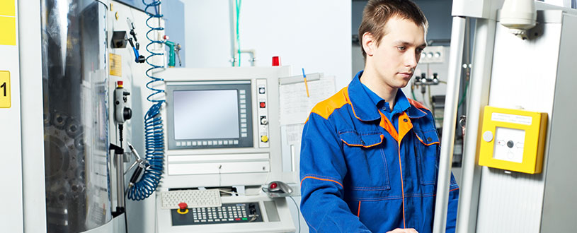
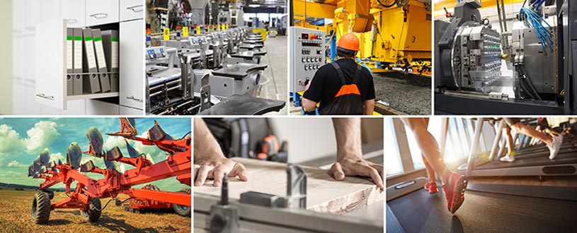
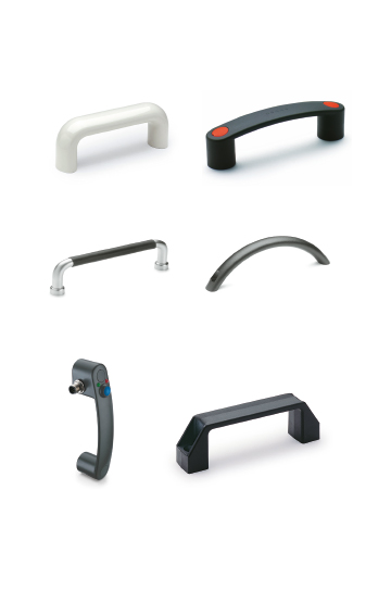
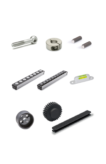
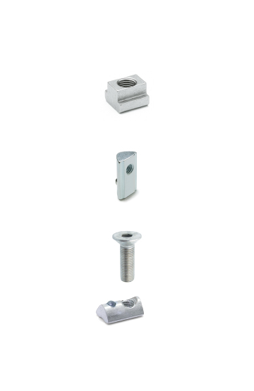
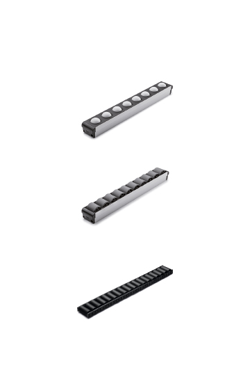
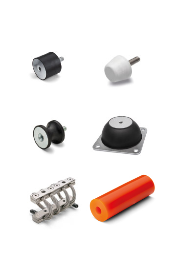
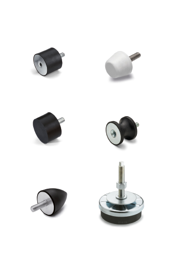
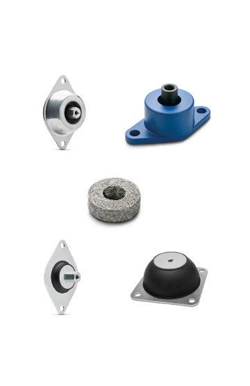
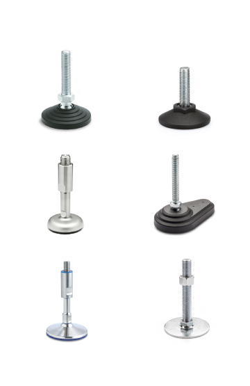
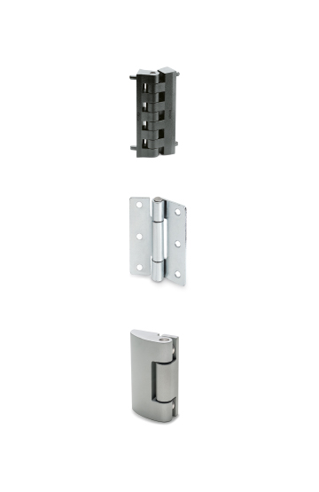
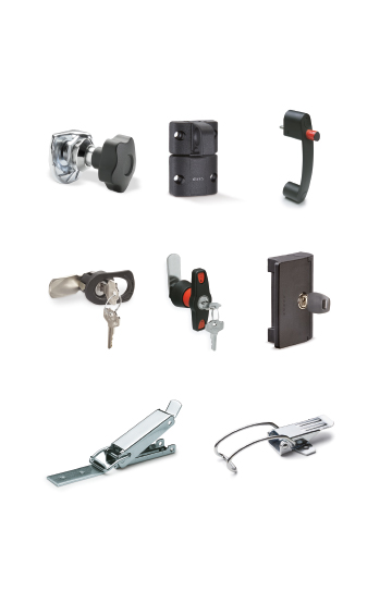
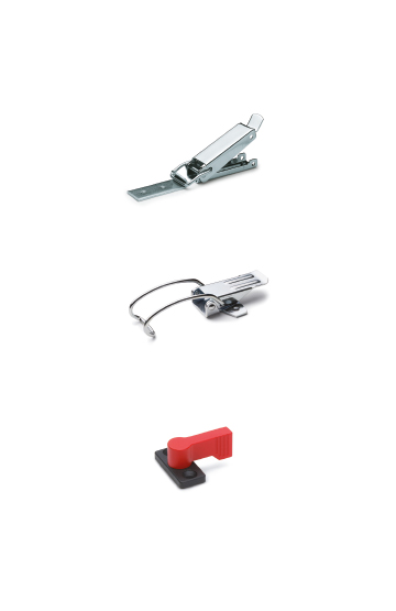
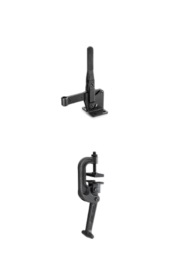
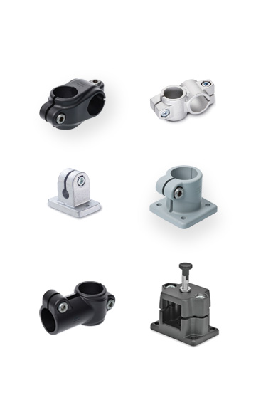
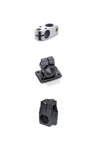
Components for construction vehicles, equipment and machinery which operate in particularly unfavourable conditions
High quality standards, precision in tolerances and care in surface finishes are requirements that ensure greater precision in operation
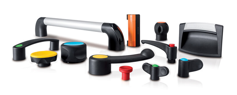
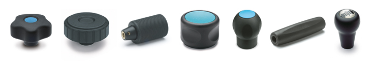
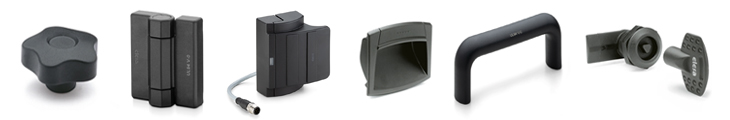
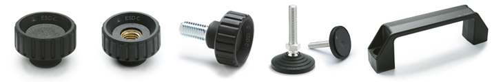
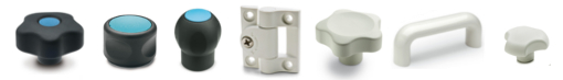
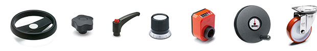
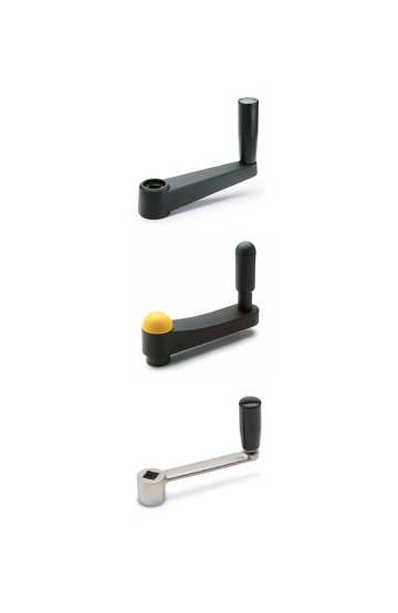
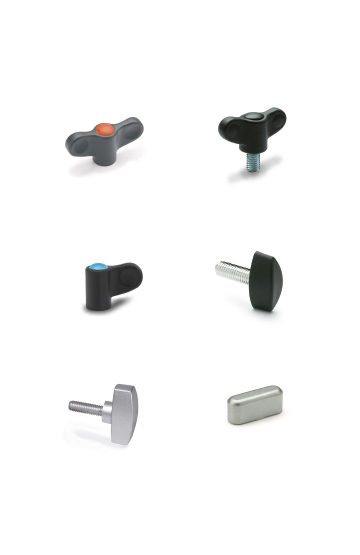
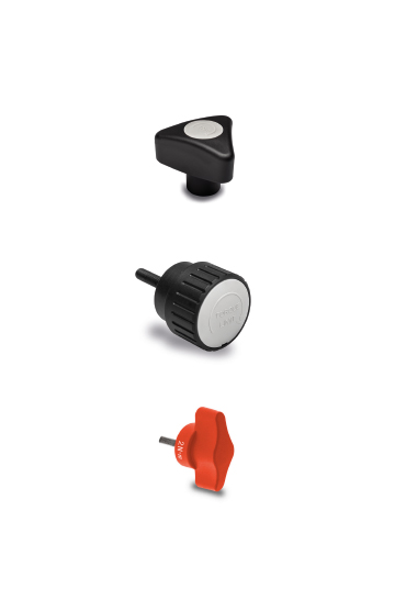
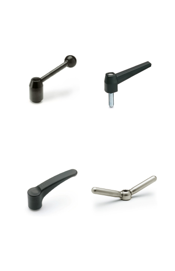
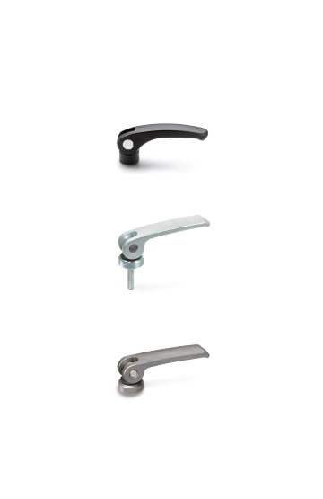
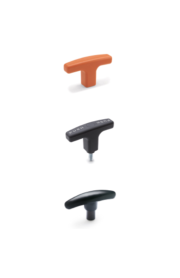
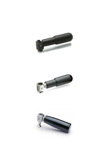
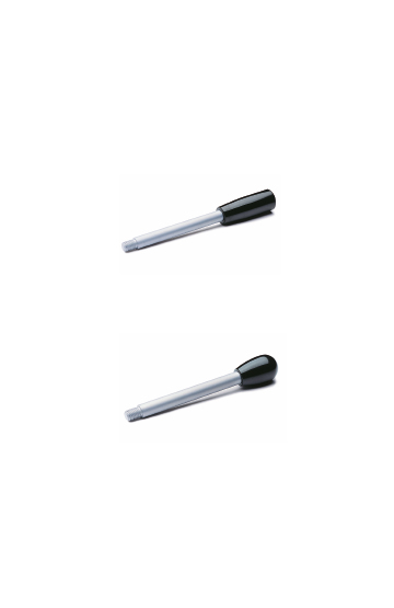
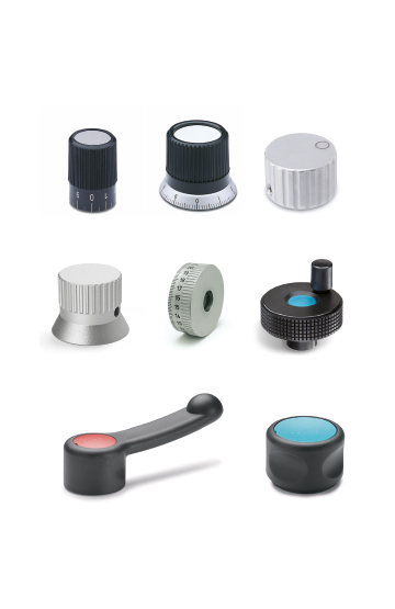
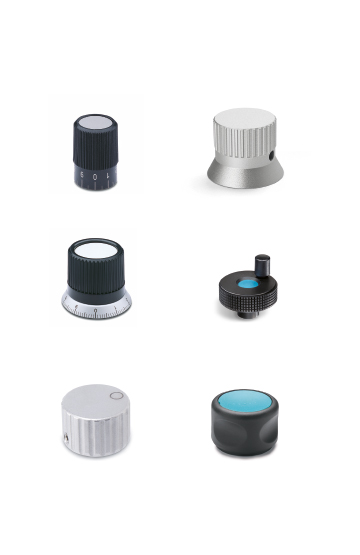
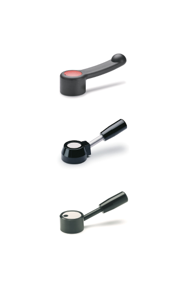
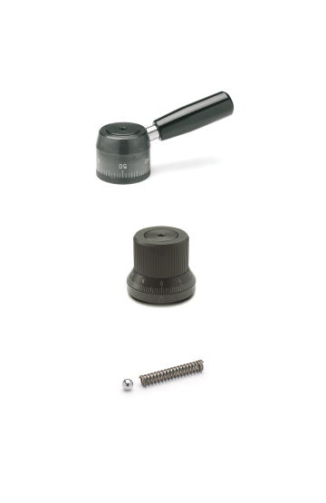
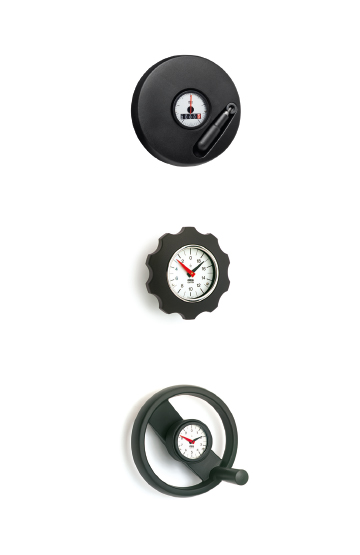
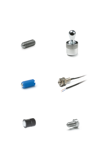
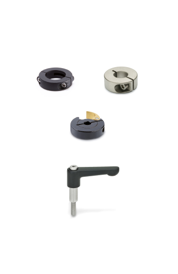
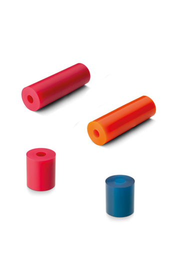
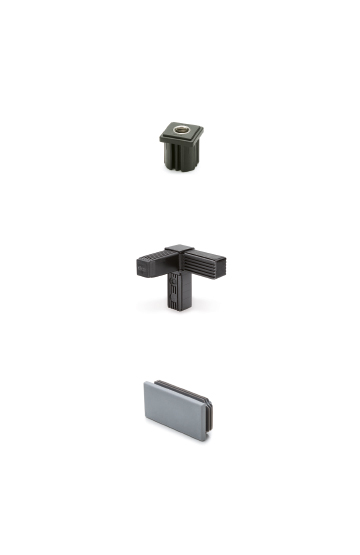
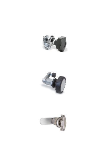
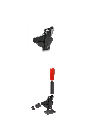
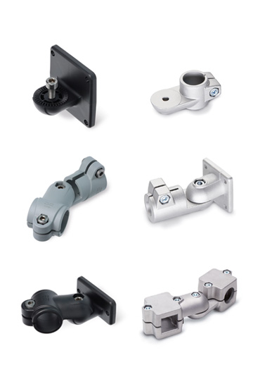
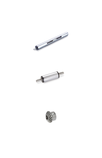
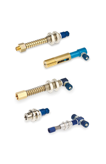
Clamping knobs, adjustable handles and self-locking pins for clamping operations in the field of photography, lighting and electronic equipment
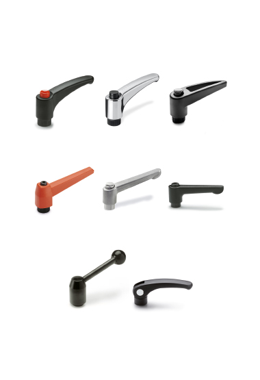
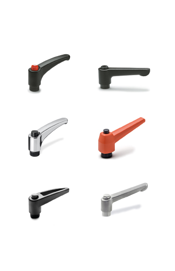
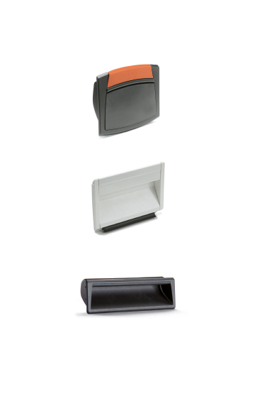
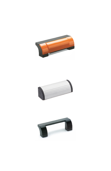
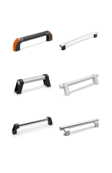
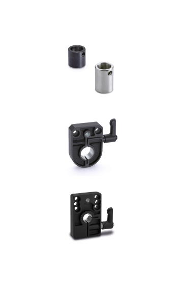
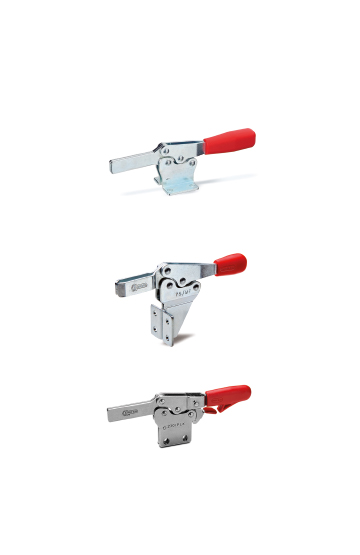
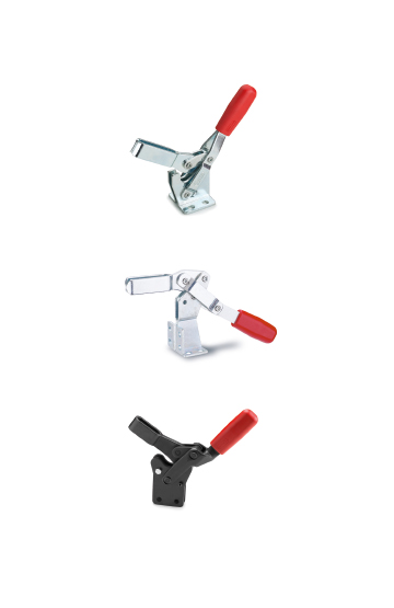
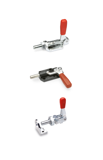
Components to perform clamping and locking operations on machinery or equipment. Ergonomics and design combined with colours
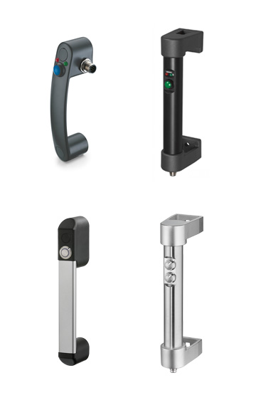
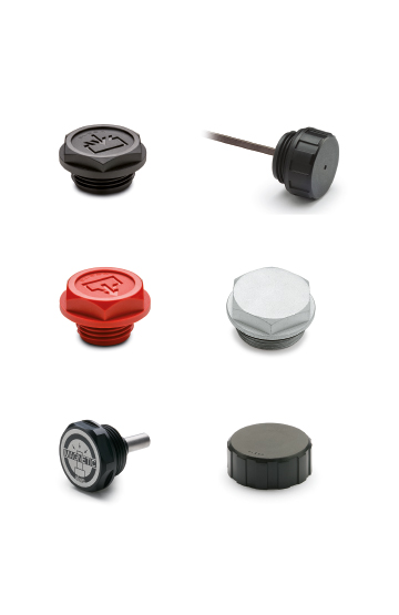
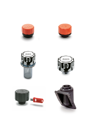
Glass-fibre reinforced polyamide based (PA) technopolymer certified self-extinguishing UL-94 V0, black colour.
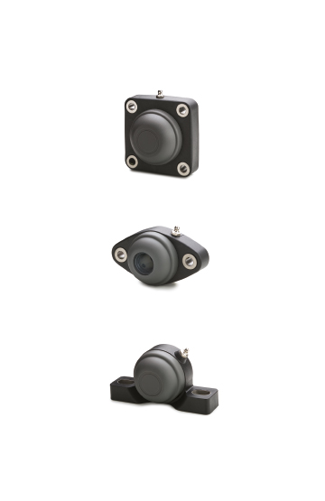
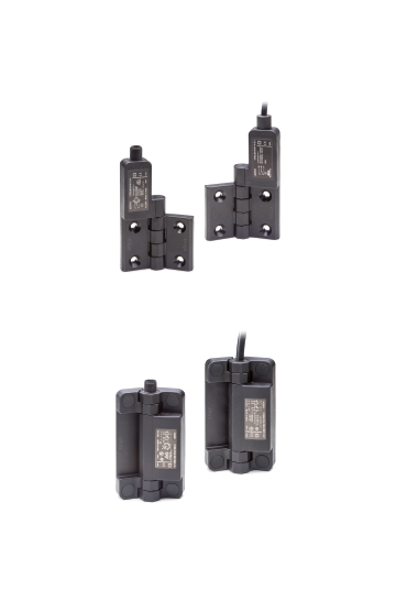
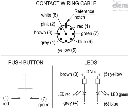
The device is made up of a normally open contact (NO).
Switching takes place by pressing the purple button (bistable contact), and remains switched until pressed again.
Contact resistance: max. 0.050 Ω
Isolation resistance: min. 1 GΩ at 500 VDC
A red Led and a green Led can be configured through external logic to indicate the switch status.
Voltage range 24 Vdc ± 15%
Technopolymer, grey-black colour, matte finish. Supplied assembled, removable by a screwdriver.
IP 65 protection class, according to EN 60529
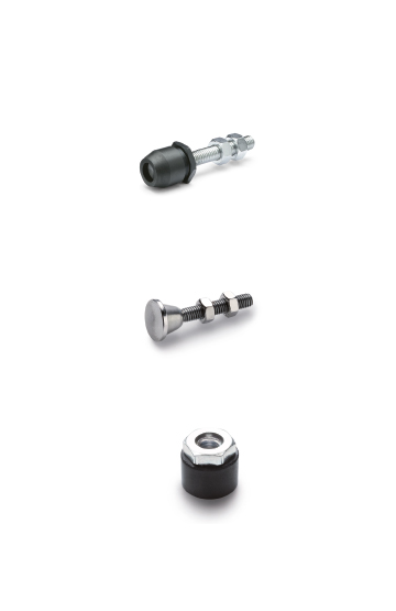
Pass-through holes for cylindrical-head screws with hexagon socket.
8 pole cable UL: AWG22 RAL9005 PVC UL AWM Style 1569/2517.
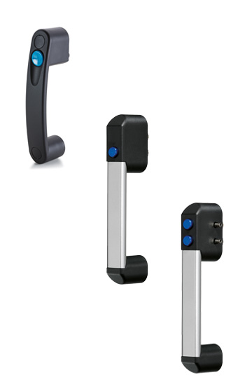
This handle is used when it is necessary for the switching to be prolonged over time.
Through external logic, the Leds can be configured to indicate the specific status of the button. Example: button in neutral position green Led on, button switched on red Led off.
The mechanical life of the button is 200000 cycles.
The product has been manufactured in compliance with the EN60947-1:2007: +A1:2021+A2:2014 EN 60947-5-1:2017 standards and the CE marking is visible on one side of the handle.
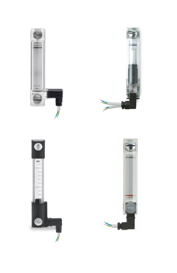
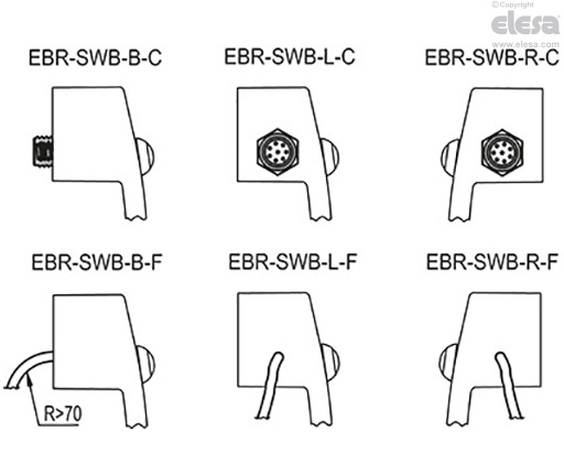
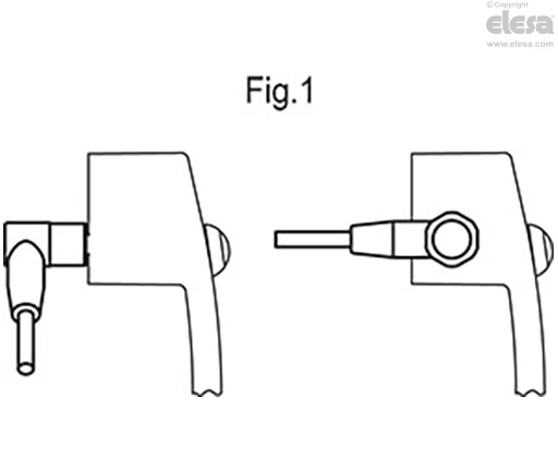
In case of use of an extension with angled connector, the direction of the cable output is shown in the Fig.1.
EBR-SWB handle can be assembled with EBR neutral handle.
Tensile stress and impact strength: F1, F2, L1 and L2 values reported in the table are the result of breaking tests carried out with the appropriate dynamometric equipment under the test conditions shown in the figure with ambient temperature.
| Electrical Features | |||
| Load | Voltage | Current | Max Cycles |
| Resistive | 12 Vdc | 4 A | 200000 |
| Resistive | 48 Vdc | 1 A | 200000 |
| Resistive | 48 Vdc | 2 A | 100000 |
| Resistive | 48 Vdc | 3 A | 75000 |
| Logic level | 5 Vdc | 10 mA | 200000 |
| DWV | 1000 Vrms | - | - |
| Short circuit conditioned current: 1000 A | |||
*For the connector version the maximum allowed voltage is 24 V and the maximum allowed current is 2A.