Close


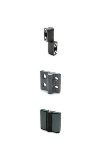
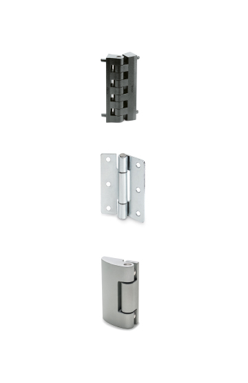
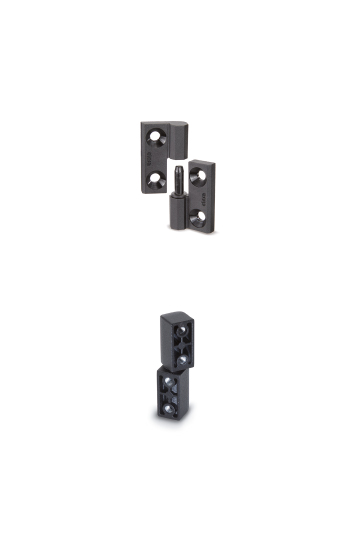
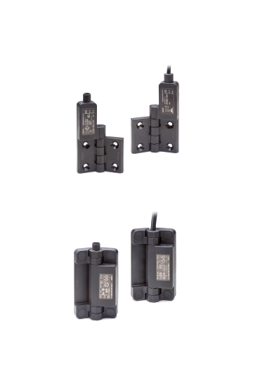
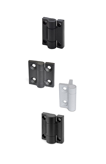

































































CFDX
Hinges for narrow jamb
SUPER-Technopolymer


Main specifications
Material
Glass-fibre reinforced polyamide based (PA) SUPER-technopolymer, black colour, matte finish.
Rotating pin
Glass-fibre reinforced polyamide based (PA) SUPER-technopolymer.
Standard executions
For mounting with flush door and jamb (Fig. 1).
- CFDX-C-B: stainless steel nuts with a threaded hole in the narrow body (jamb); brass bushings with a blind threaded hole in the wide body (door).
- CFDX-C-p: stainless steel threaded studs on the narrow body (jamb), brass bushings with blind threaded holes on the wide body (door).
- CFDX-C-SH: pass-through-holes with housing for countersunk-head screws on the narrow body (jamb), brass bushings with blind threaded holes on the wide body (door).
For mounting with the door (max. thickness = 5 mm) flush against the jamb (Fig. 2).
- CFDX-R-B: stainless steel nuts with a threaded hole in the narrow body (jamb); brass bushings with a blind threaded hole in the wide body (door).
- CFDX-R-p: stainless steel threaded studs on the narrow body (jamb), brass bushings with blind threaded holes on the wide body (door).
- CFDX-G-R-SH: pass-through holes with housing for countersunk-head screws on the narrow body (jamb), brass bushings with blind threaded holes on the wide body (door).
General information
Features and applications
The hinge (registered design) is made up of two bodies of different sizes (one wide and one narrow) for use, for example, on structures with a narrow jamb.
The type of mounting makes tampering by third parties difficult.
SH versions are supplied disassembled to facilitate mounting.
Rotation angle (approximate value)
Max 195° (-5° and +190° being 0° the condition where the two interconnected surfaces are on the same plane). Do not exceed the rotation angle limit so as not to prejudice the hinge mechanical performance.
Test for resistance | Axial Stress | Radial Stress | 90° Angled Stress | |||
 |  |  | ||||
| Description | Maximum working load | Breaking load Ra [N] | Maximum working load Er [N] | Breaking load Rr [N] | Maximum working load E90 [N] | Breaking load R90 [N] |
| CFDX-C.40-B-M5 | 498 | 2859 | 399 | 1633 | 401 | 1373 |
| CFDX-C.40-p-M5x14.5 | 341 | 2924 | 417 | 1563 | 405 | 1545 |
CFDX-C.40-SH.5 | 451 | 2759 | 417 | 1579 | 473 | 1356 |
CFDX-C.50-B-M6 | 776 | 2837 | 1219 | 1738 | 1747 | 2165 |
| CFDX-C.50-p-M6x14.5 | 759 | 2596 | 1283 | 2263 | 1779 | 2591 |
| CFDX-C.50-SH.6 | 969 | 2836 | 1152 | 3556 | 1763 | 2903 |
| CFDX-C.60-B-M6 | 837 | 3540 | 1112 | 2072 | 1824 | 2158 |
| CFDX-C.60-p-M6x14.5 | 856 | 3396 | 896 | 1997 | 1933 | 2436 |
| CFDX-C.60-SH.6 | 928 | 3218 | 1163 | 3411 | 1502 | 4773 |
Test for resistance | Axial Stress | Radial Stress | 90° Angled Stress | |||
| | | ||||
| Description | Maximum working load Ea [N] | Breaking load Ra [N] | Maximum working load Er [N] | Breaking load Rr [N] | Maximum working load E90 [N] | Breaking load R90 [N] |
| CFDX-R.40-B-M5 | 571 | 2592 | 495 | 1480 | 555 | 1380 |
| CFDX-R.40-p-M5x14.5 | 427 | 2562 | 455 | 1698 | 520 | 1413 |
| CFDX-R.40-SH.5 | 408 | 2861 | 497 | 1541 | 525 | 1443 |
| CFDX-R.50-B-M6 | 1150 | 3008 | 1263 | 1782 | 1767 | 2422 |
| CFDX-R.50-p-M6x14.5 | 956 | 3265 | 1321 | 2682 | 1762 | 2640 |
| CFDX-R.50-SH.6 | 1137 | 3069 | 1056 | 3240 | 1670 | 2682 |
| CFDX-R.60-B-M6 | 947 | 3148 | 1210 | 2323 | 1551 | 2286 |
| CFDX-R.60-p-M6x14.5 | 649 | 3077 | 1123 | 2039 | 1908 | 2492 |
| CFDX-R.60-SH.6 | 556 | 3741 | 1196 | 3584 | 1831 | 4855 |
Instructions for use
Assembly instructions (SH versions)
- Secure the narrow body to the jamb and the wide body to the door.
- Use a suitable tool to insert the rotating pin from the side where the diametric enlargement is not present until it locks in the hinge body.

Models all rights reserved in accordance with the law. Always mention the source when reproducing our drawings and photos.