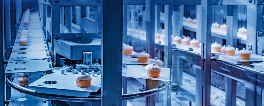


SELF-SANITISATION AGAINST BACTERIA AND FUNGI
Close
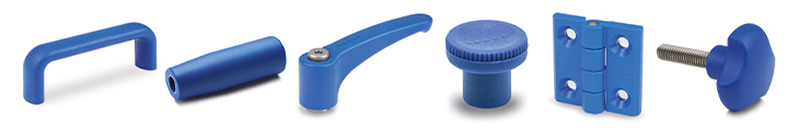
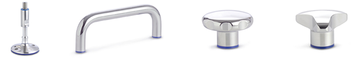
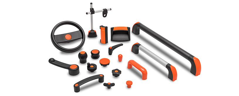
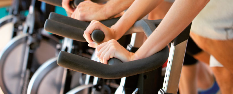
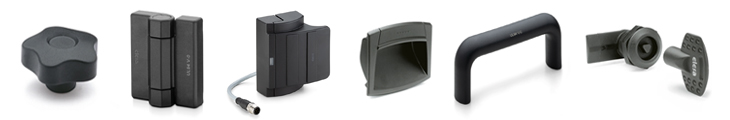
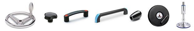
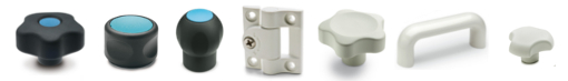
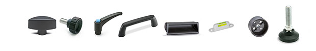
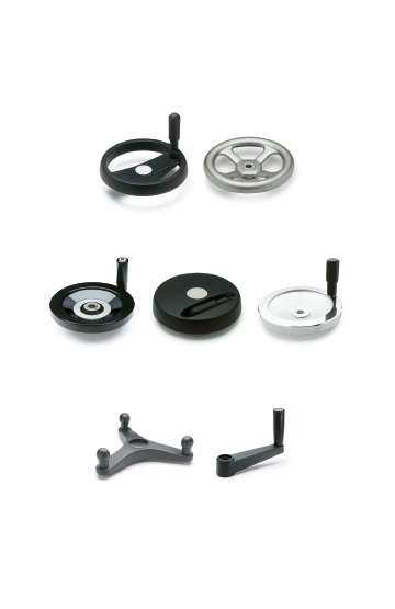
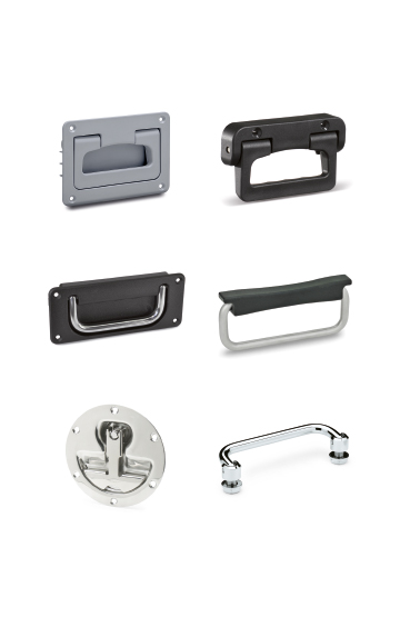
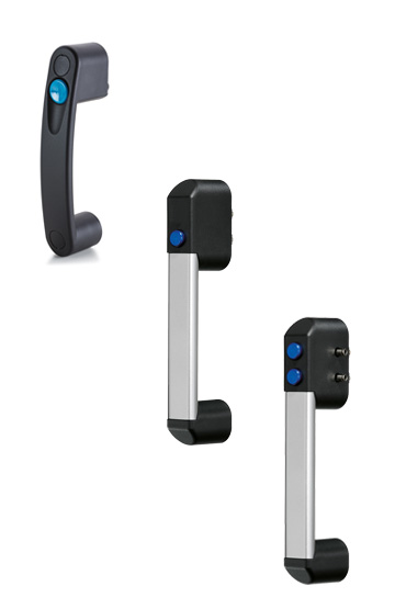
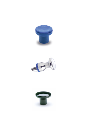
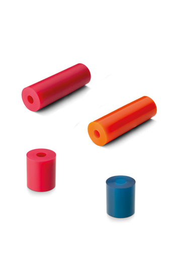
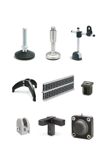
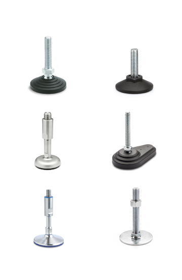
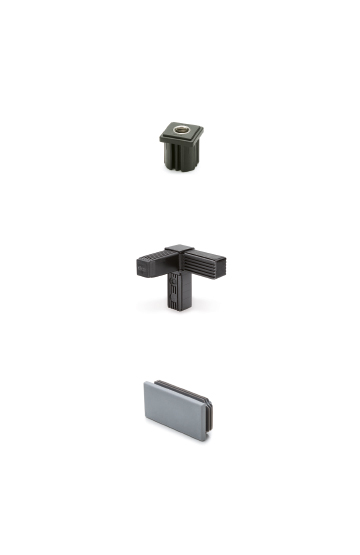
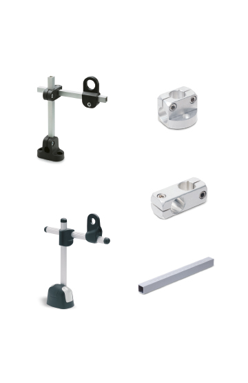
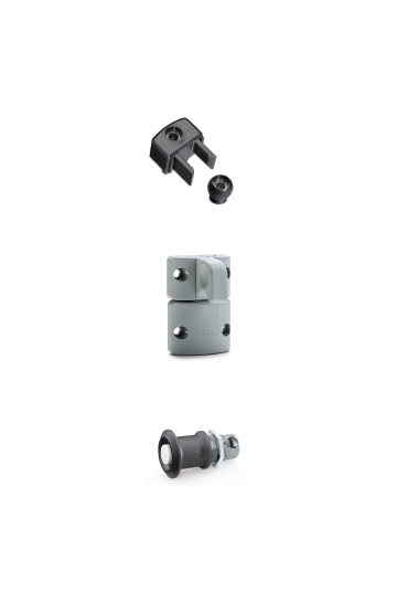
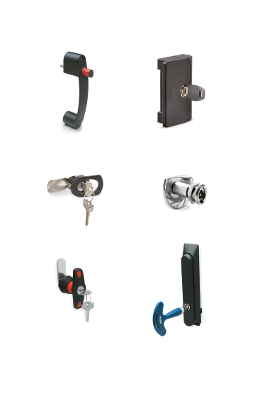
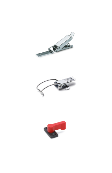
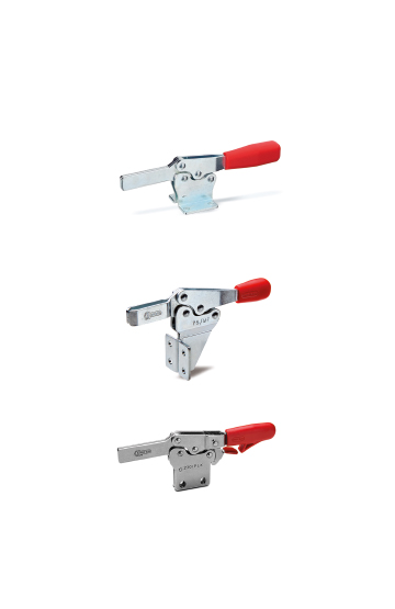
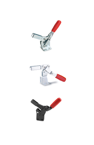
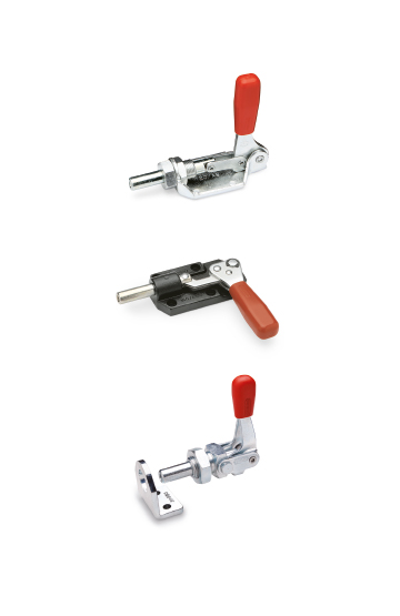
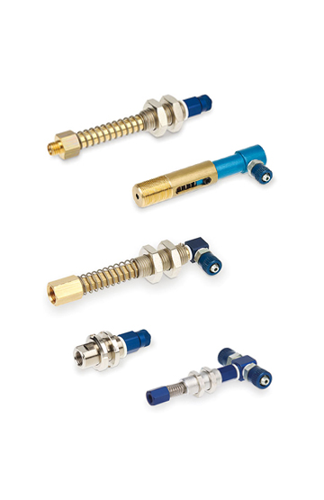
Components for manoeuvring, clamping and locking operations on equipment, including sports equipment and furniture in the nautical sector.
Corrosion resistance, ergonomics, compact shapes and great care in the choice of materials and finishes ease of cleaning
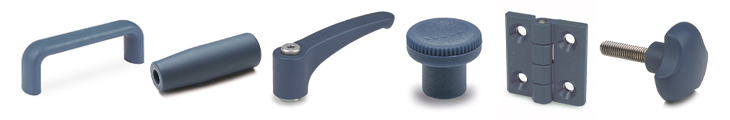
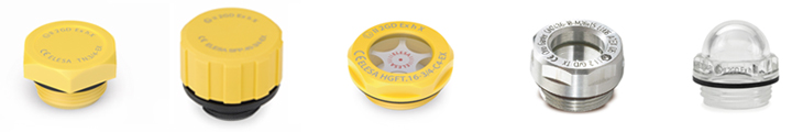
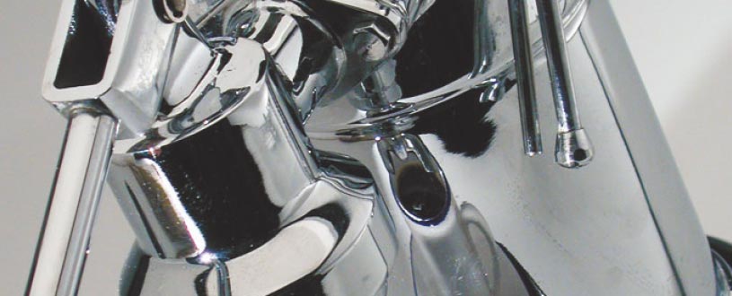
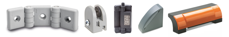
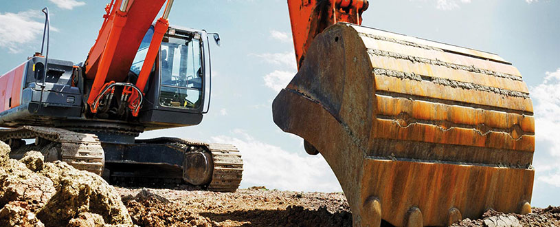
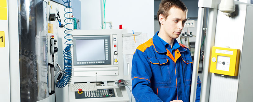
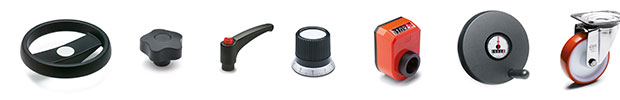
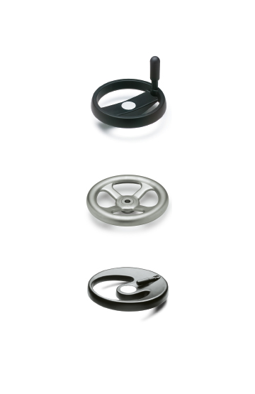
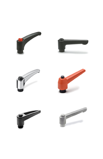
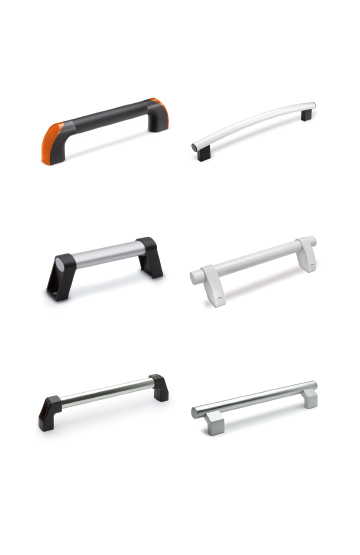
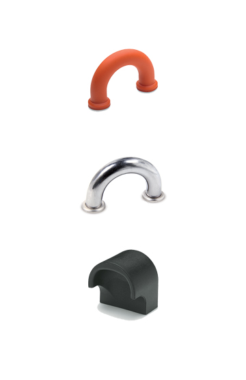
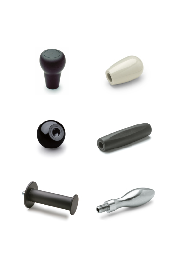
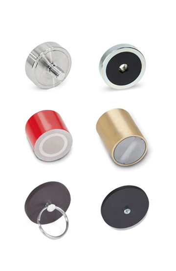
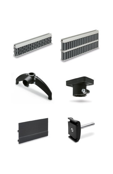
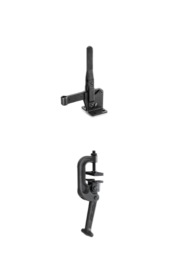
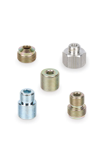
Components for construction vehicles, equipment and machinery which operate in particularly unfavourable conditions
High quality standards, precision in tolerances and care in surface finishes are requirements that ensure greater precision in operation
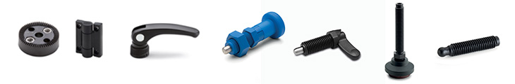
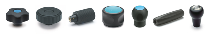
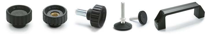
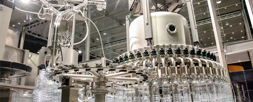
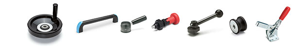
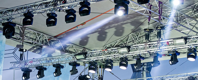
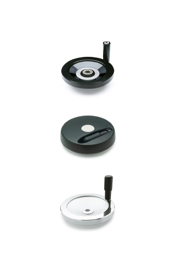
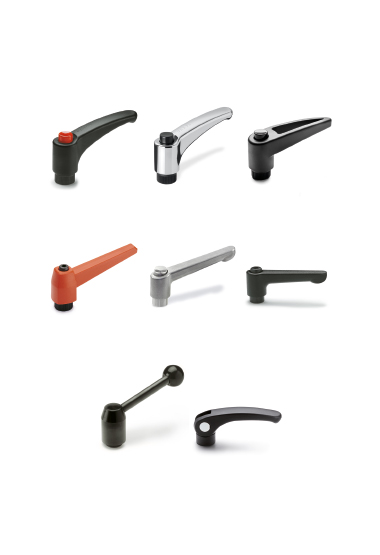
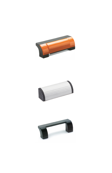
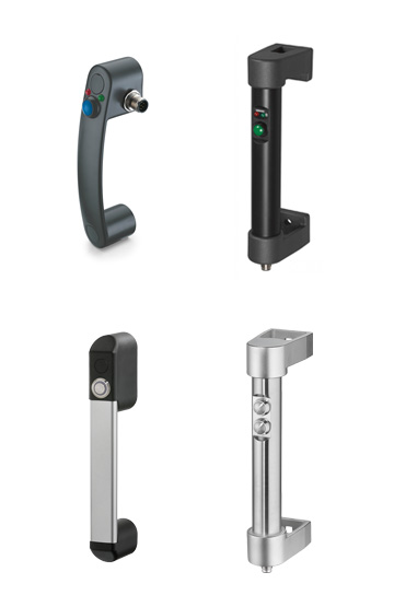
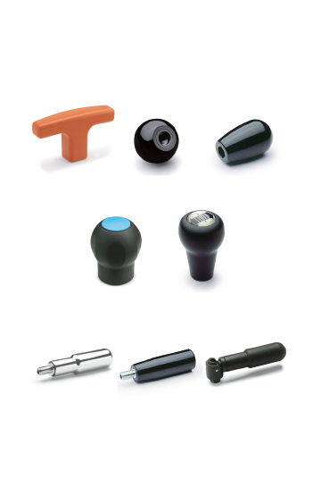
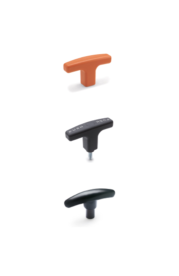
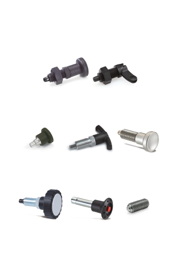
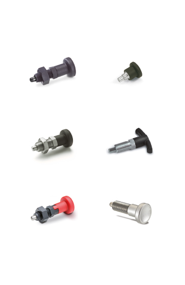
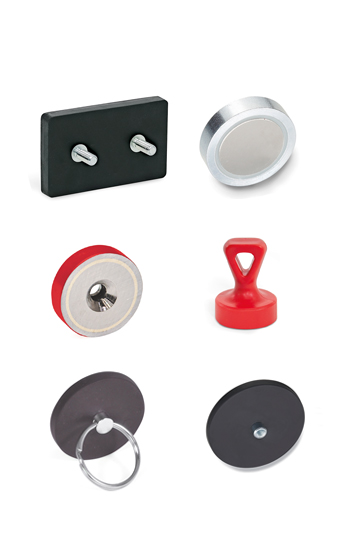
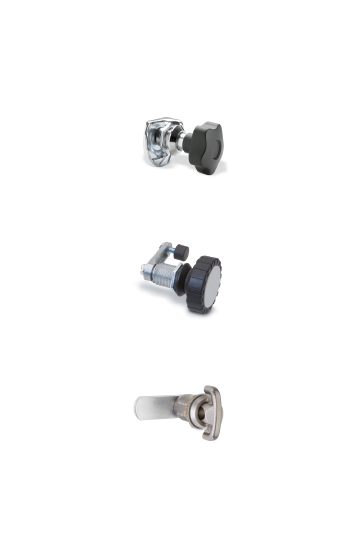
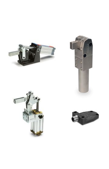
Clamping knobs, adjustable handles and self-locking pins for clamping operations in the field of photography, lighting and electronic equipment
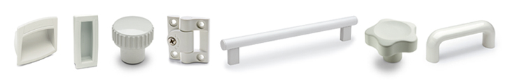
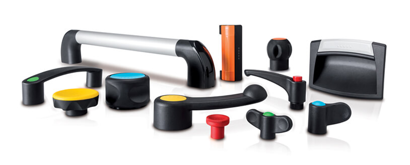
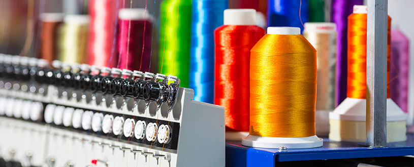
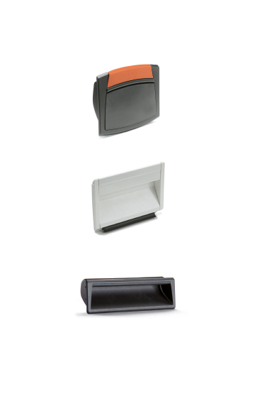
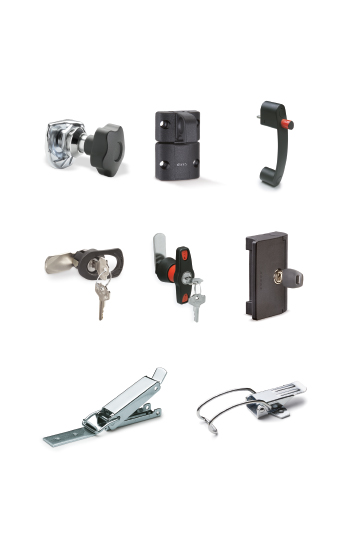
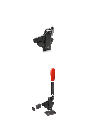
Components to perform clamping and locking operations on machinery or equipment. Ergonomics and design combined with colours
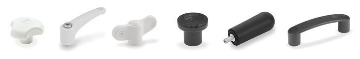
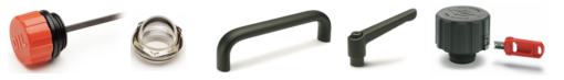
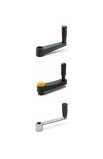
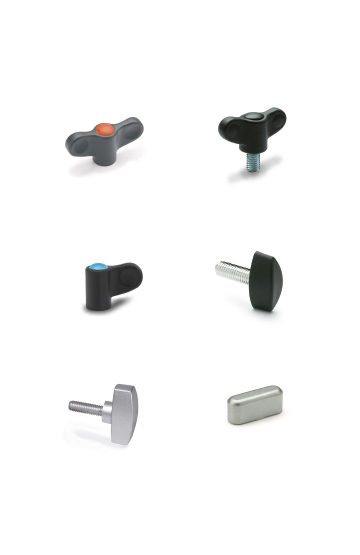
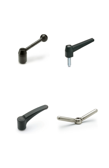
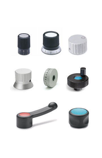
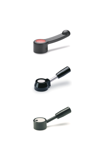
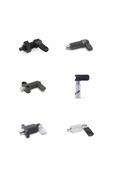
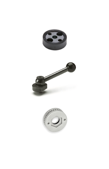
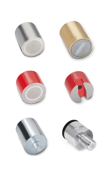
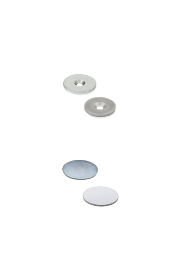
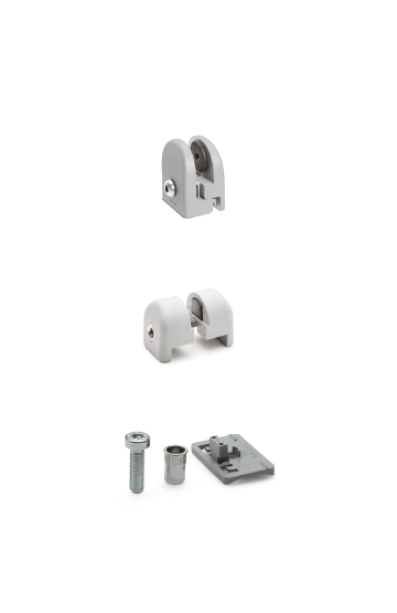
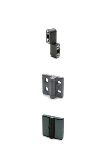
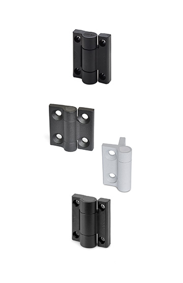
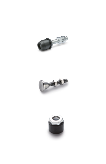
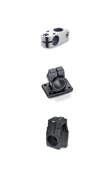
Knurled anodised aluminium, black colour.
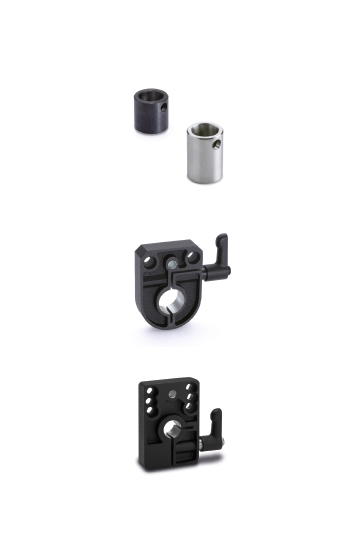
Black-oxide steel. Assembly by means of three holes for M5 cylindrical head screws with hexagon socket.
Black anodised matte aluminium.
Assembly to the bushing by means of two countersunk head screws.
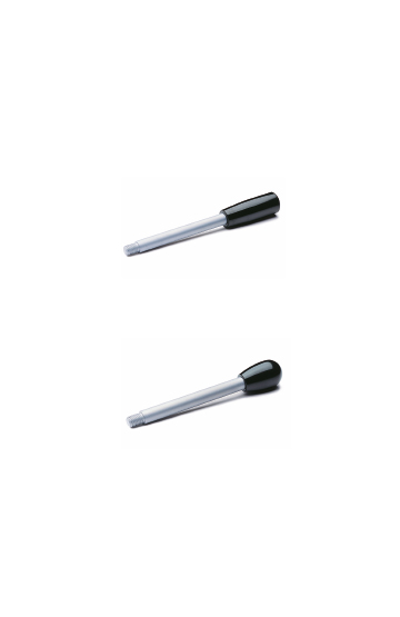
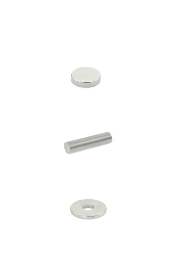
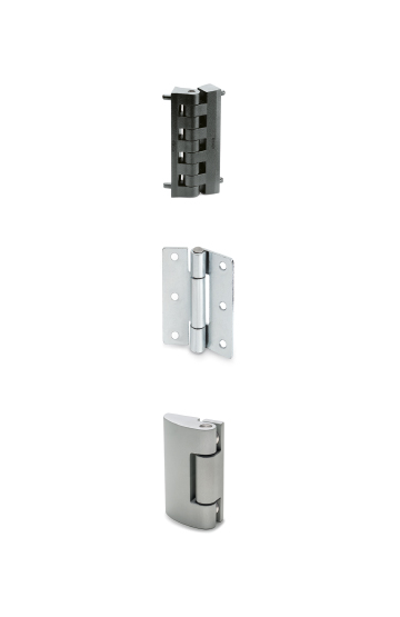
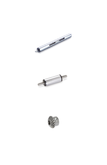
Ground and hardened steel.
Steel bushing. H7 reamed hole and keyway in compliance with DIN 6885/2 tolerance P9. Assembly to the spindle by means of a keyway or a transversal pin.
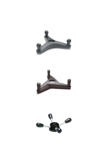
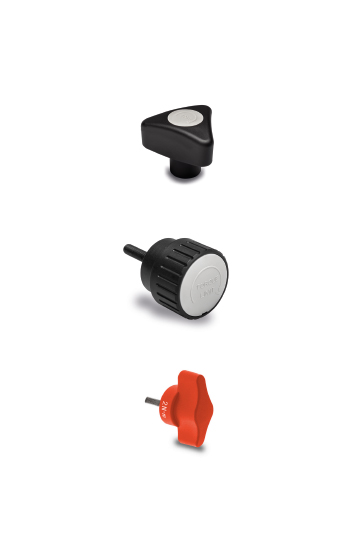
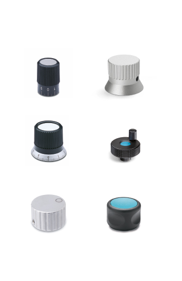
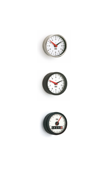
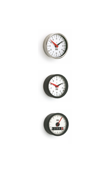
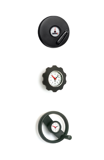
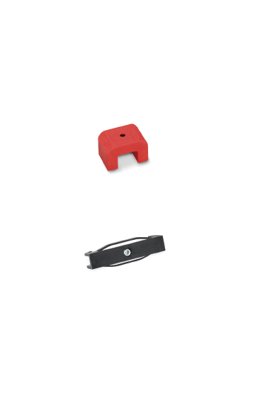
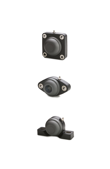
In GN 700-A and GN 700-S the triangular index is marked exactly in the middle, at the same distance from the base assembly holes (60°).
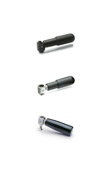
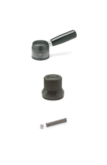
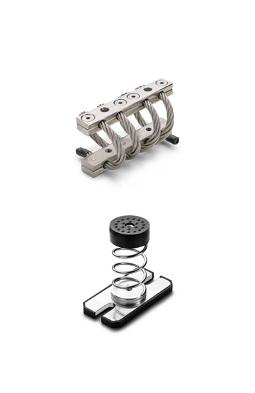
GN 700 locking and continuous control indexing mechanisms are used to control machine spindles for clockwise and anti-clockwise rotation and to keep the spindle in a given position even when vibrations or torque make it turn. Therefore, the locking system prevents the spindle from making uncontrolled movements and offers enhanced safety protection against rotation. The locking system, which operates on the principle of the two directional free wheel with lock, is used to transmit the movement without clearance in both directions.
This locking and continuous control knob cannot be used where the spindle rotates before the adjustment is performed or as a bearing for the controlled spindle or in case of high-intensity vibrations.
By turning the control knob, one of the two release-pins (depending on the rotation direction) pushes the stop cylinder against the central spring into an inactive position that allows the bushing and therefore the spindle to rotate freely.
The second release-pin limits the movement of the other stop cylinder and, at the same time, ensures that the bushing is driven and rotated with precision while the first pin remains in the inactive position until the rotation ends, when the spring resets the lock.
The scale ring, connected to the assembly hole, accurately positions the machine spindle. Thus, infinite adjustments can be performed to cover all operating requirements.
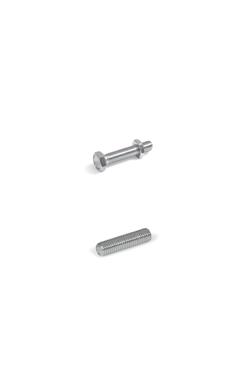
To ensure perfect operation of the GN 700 element, the base should be assembled exactly perpendicular to the spindle axis.