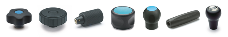


SELF-SANITIZATION AGAINST BACTERIA AND FUNGI
Close
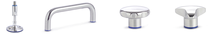
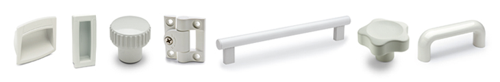
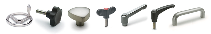
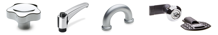
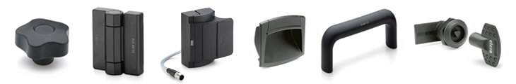
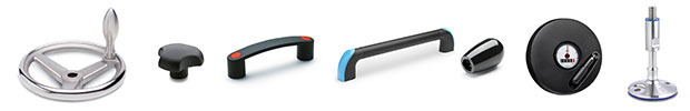
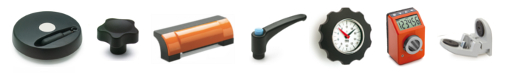
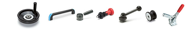
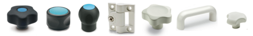
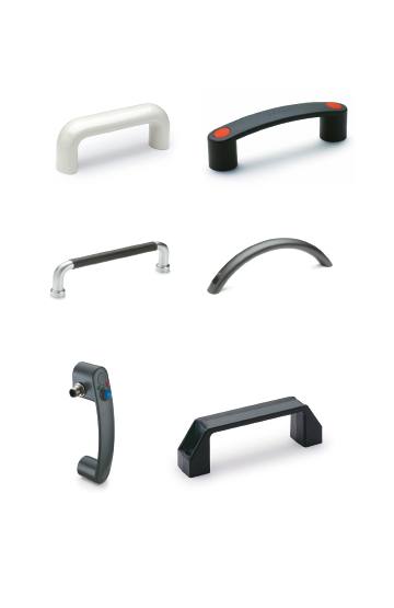
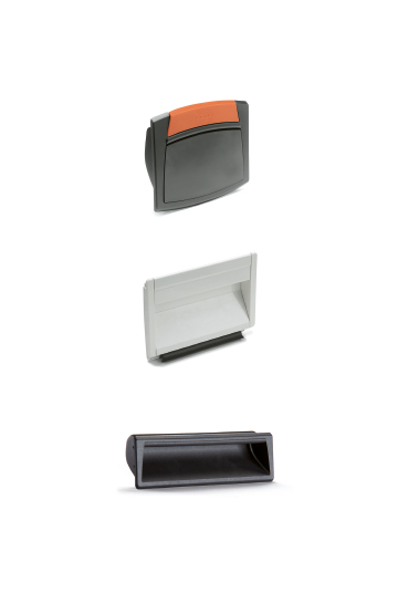
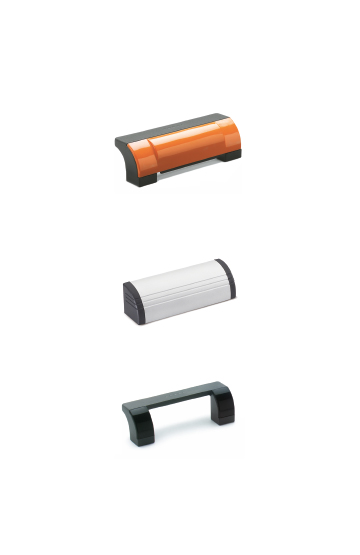
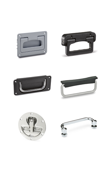
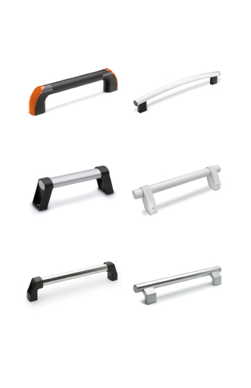
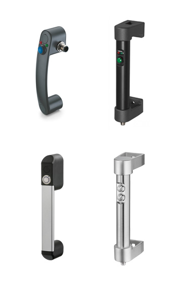
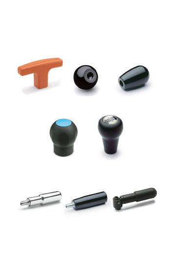
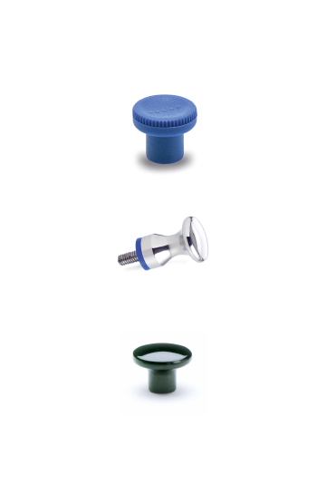
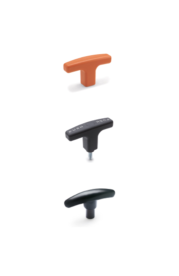
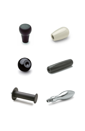
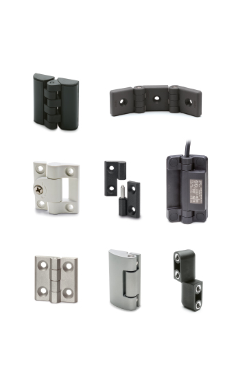
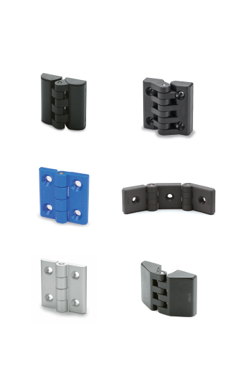
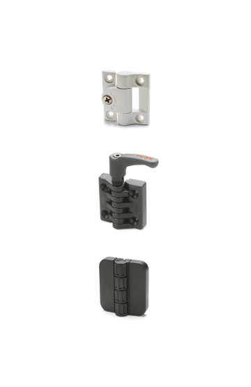
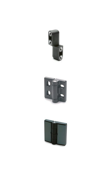
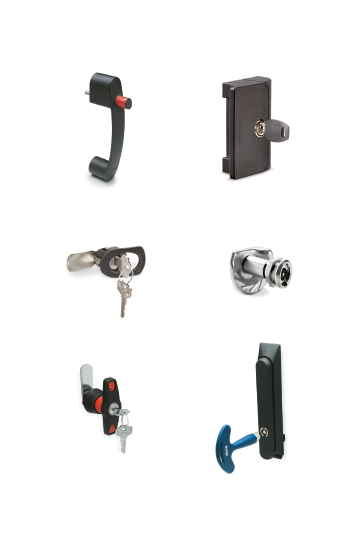
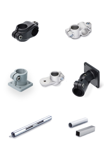
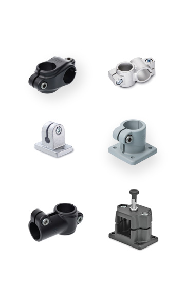
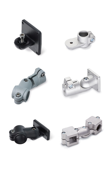
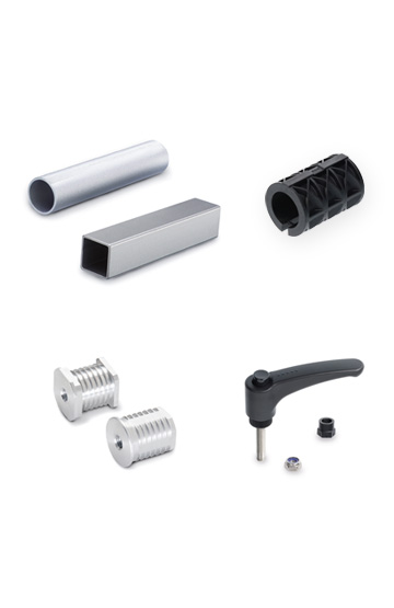
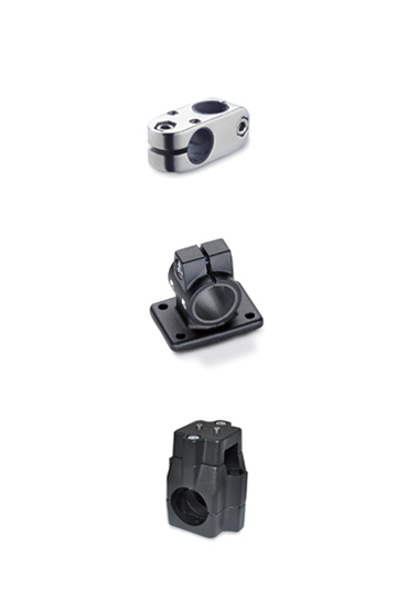
Corrosion resistant, ergonomic, compact shapes in choice materials with easy-clean finishes
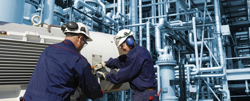
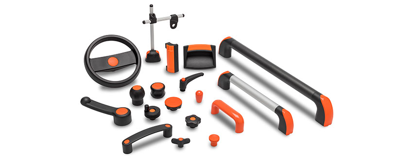
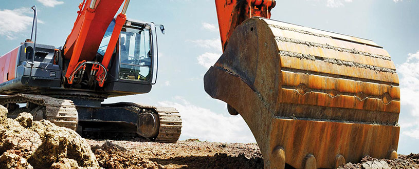
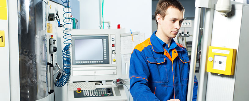
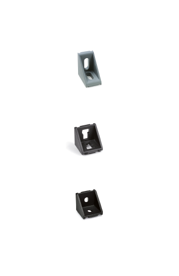
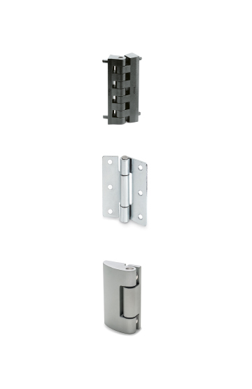
Components for construction vehicles, equipment and machinery
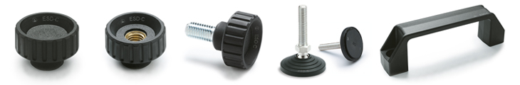
AISI 304 stainless steel, matte finish.
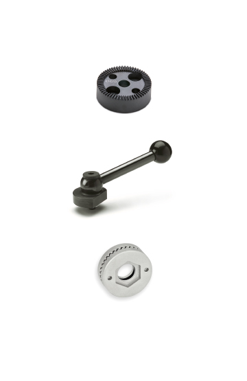
Self-lubricating bronze.
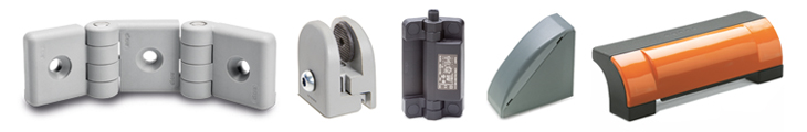
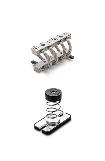
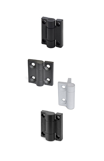
The maximum load of the multiple joint hinges shown below applies in normal conditions of use and serves as a guide for other applications.
The resulting force results in a slight elastic deformation that can be offset using the adjustment options where necessary.

| Resistance tests | Axial Stress | Radial Stress |
| Description | FA [N] | Fr [N] |
| GN 7237-40 | 175 | 650 |
| GN 7237-50 | 175 | 750 |
| GN 7237-60 | 150 | 550 |
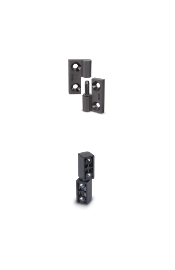
GN 7237 pantograph jointed hinges are installed internally to the doors, shutters, or airtight containers, saving space and protecting against acts of vandalism.
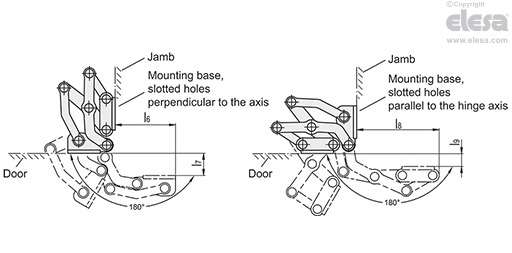
They have a 180° maximum angle of opening, which provides optimal accessibility and avoids blocking open door emergency exits.
The GN 7237 hinges are usually used in pairs. This means that for the opening of one door, a GN 7237-L hinge and a GN 7237-R hinge are used.
For increased loads, for example a large size door, they can be used with additional hinges of both types.
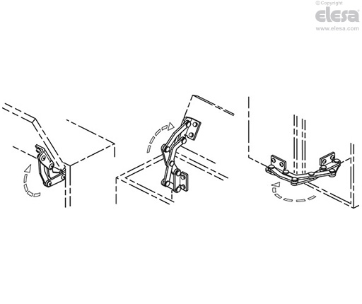
The doors or shutters can be inserted, surface-mounted, or angled.
The largest shims for the doors/jambs and the fold dimensions for the sheet construction depend on the respective type of installation.
The design variants indicated in fig. 1 and fig. 2 represent the standard installation conditions.
If the hinge installation position is changed or one of the two wall shim dimensions is smaller, the maximum obtainable dimensions change independently of each other. In some cases this allows for working with wall shim dimensions that are greater than specified when the hinge dimensions remain the same.
However, it is recommended to check the design with CAD or a configuration test.
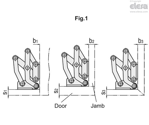
| Description | s1 max. | b1 | s2 max. | b2 max. | s3 max. | b3 max. |
| GN 7237-40 | 13 | 1 ... ∞ | 24 | 10 | 10 | 10 |
| GN 7237-50 | 19 | 1 ... ∞ | 34 | 17 | 16 | 16 |
| GN 7237-60 | 25 | 1 ... ∞ | 44 | 24 | 21 | 21 |
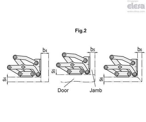
| Description | s4 max. | b4 max. | s5 | b5 max. | s6 max. | b6 max. |
| GN 7237-40 | 9 | 27 | 1 ... ∞ | 13 | 10 | 10 |
| GN 7237-50 | 17 | 35 | 1 ... ∞ | 19 | 16 | 16 |
| GN 7237-60 | 23 | 45 | 1 ... ∞ | 25 | 21 | 21 |
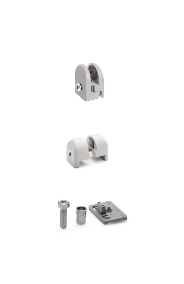
The hinge is installed via slotted holes in the mounting base, either perpendicular or parallel to the hinge axis, allowing for two different types of hinge pivot type.
The jointed hinges can be adjusted on three different planes during installation.
This allows for:
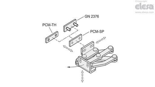
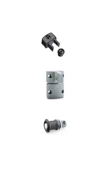
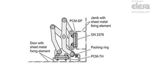
correction of the positioning via the spacer plates for hinges in stainless steel PCM-SP
Also available to fix the hinges are spacer plates with threaded holes PCM-TH and plates for jointed hinges GN 2376
The latter can also be welded or inserted from outside the jamb and fixed in position.