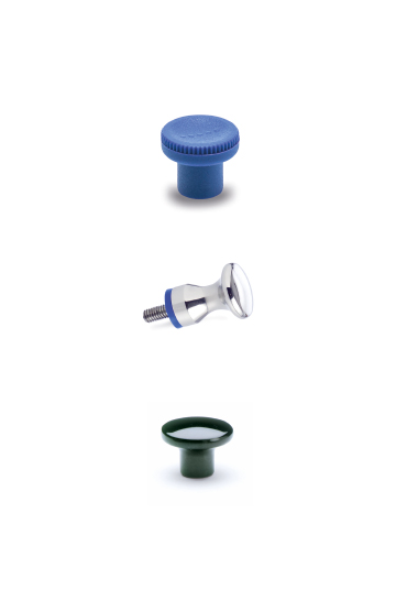


SELF-SANITISATION AGAINST BACTERIA AND FUNGI
Close
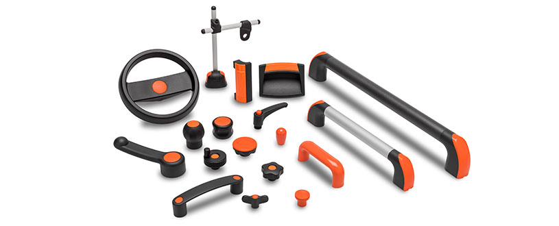
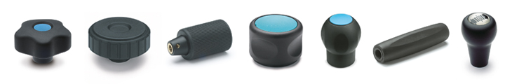
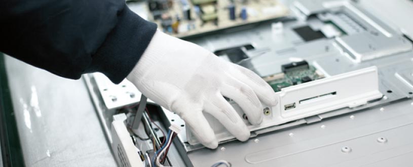
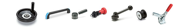
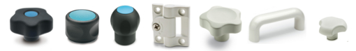
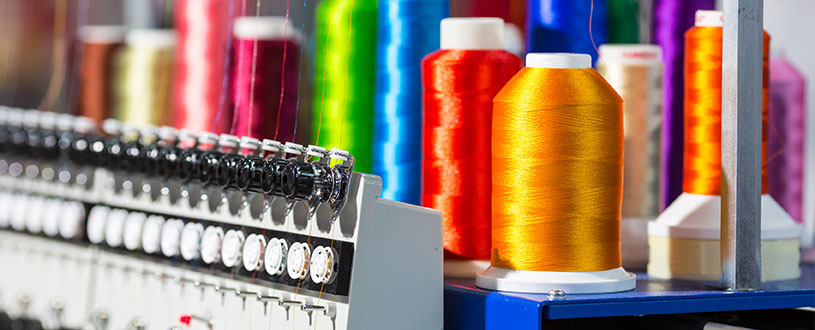
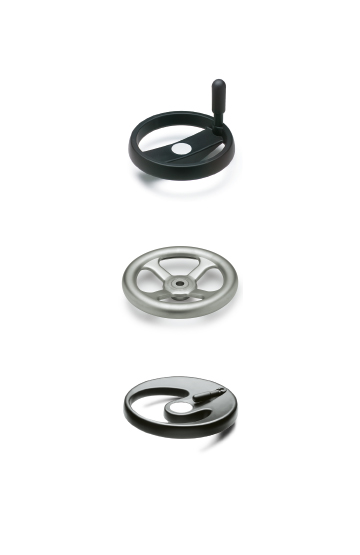
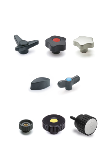
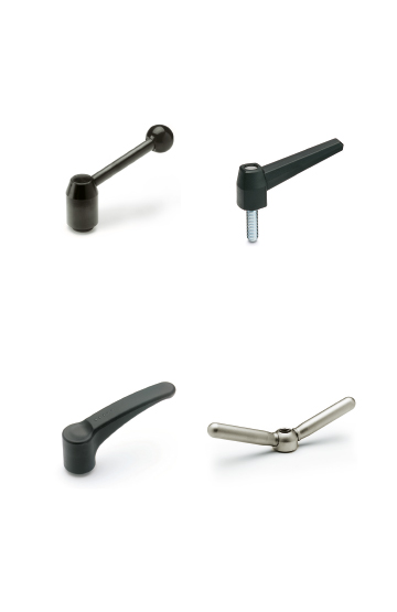
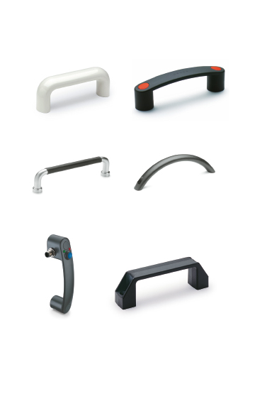
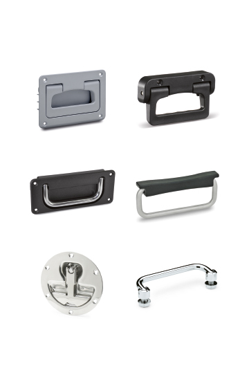
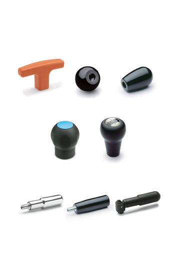
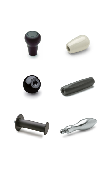
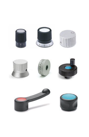
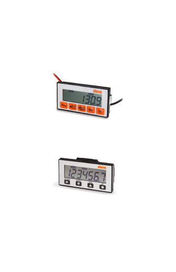
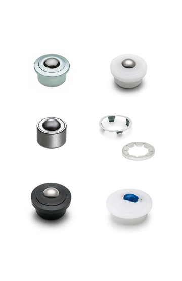
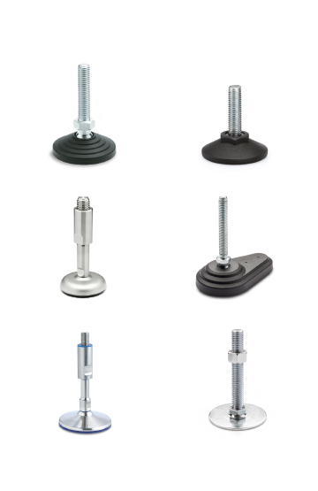
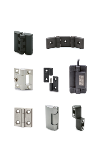
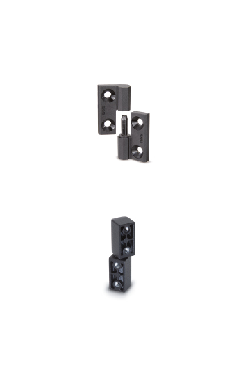
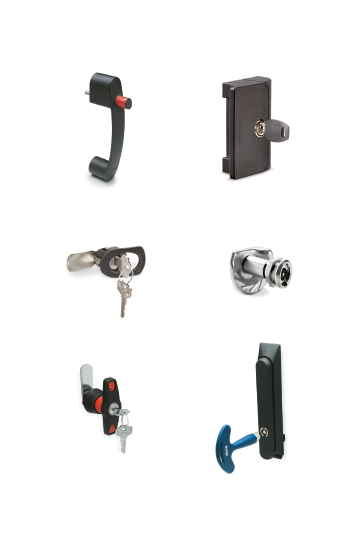
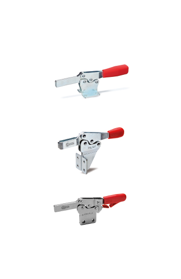
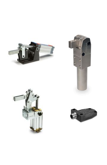
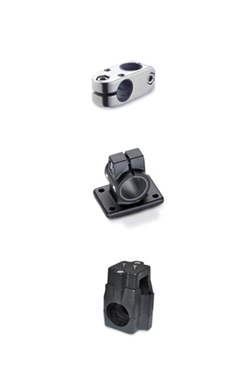
Components for manoeuvring, clamping and locking operations on equipment, including sports equipment and furniture in the nautical sector.
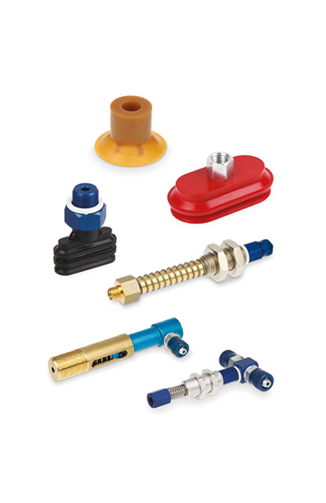
Corrosion resistance, ergonomics, compact shapes and great care in the choice of materials and finishes ease of cleaning
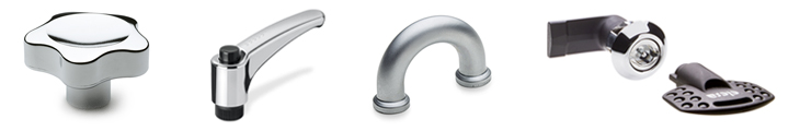
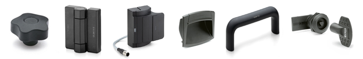
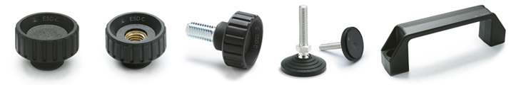
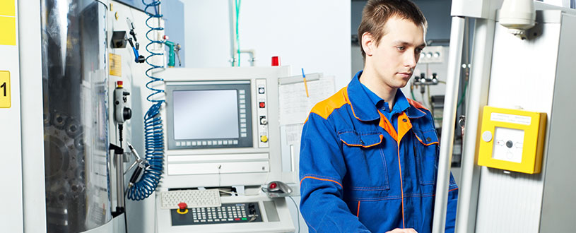
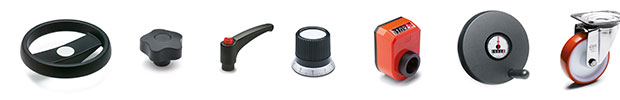
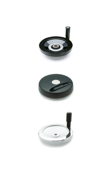
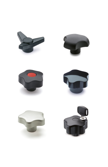
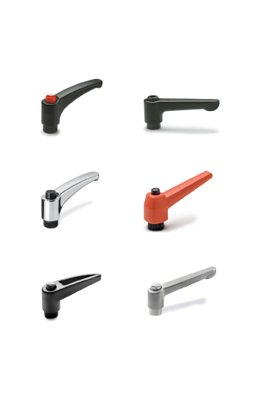
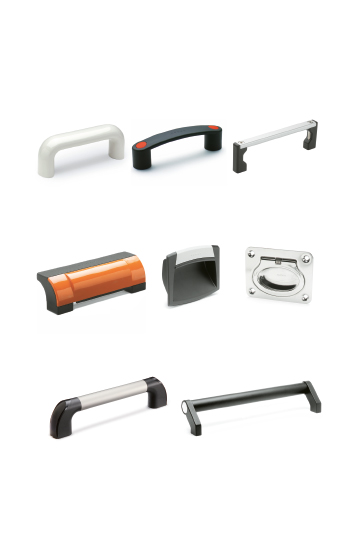
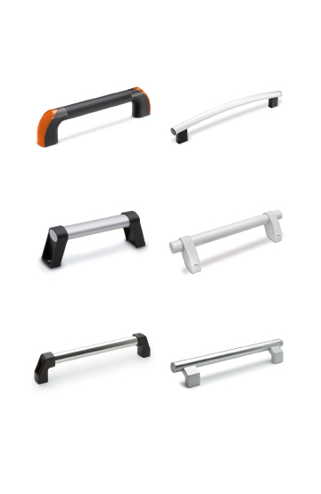
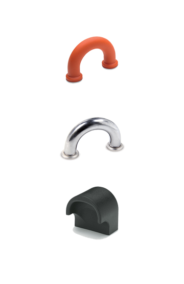
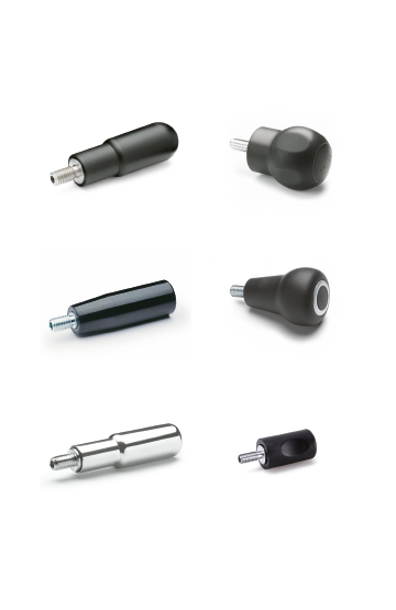
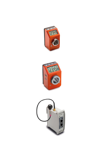
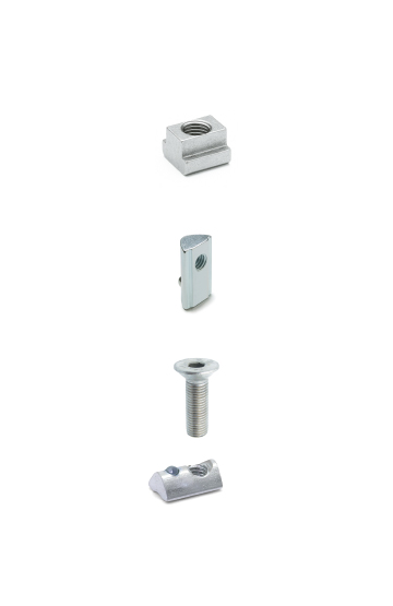
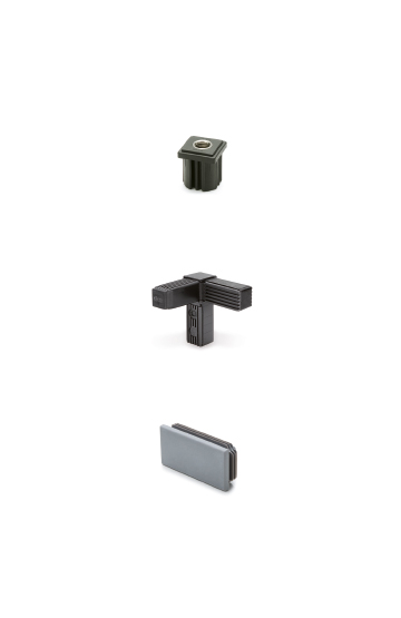
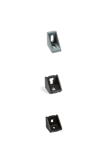
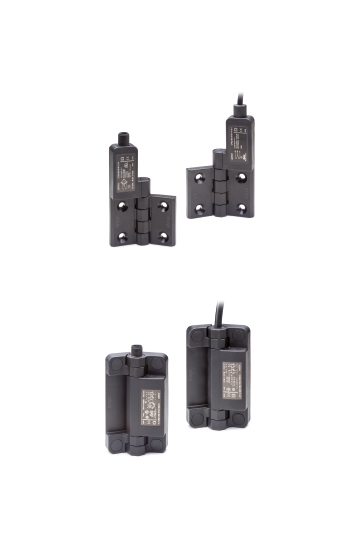
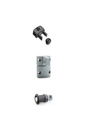
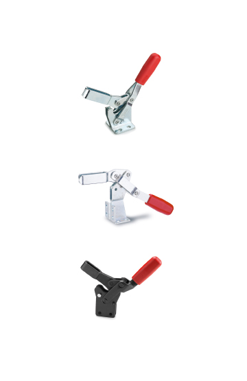
Components for construction vehicles, equipment and machinery which operate in particularly unfavourable conditions
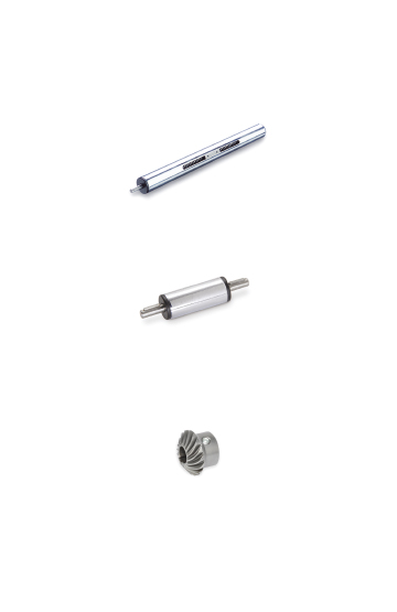
High quality standards, precision in tolerances and care in surface finishes are requirements that ensure greater precision in operation
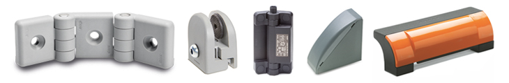
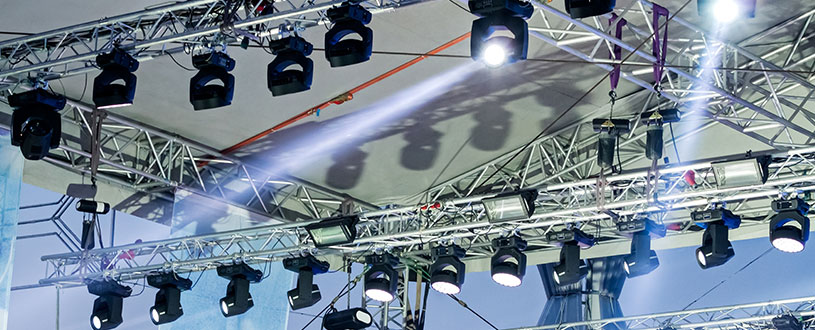
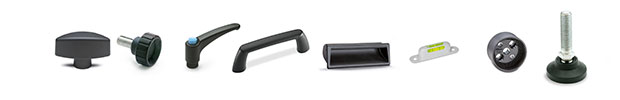
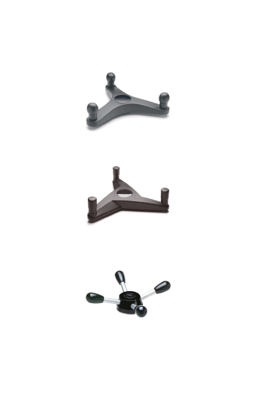
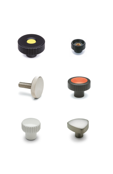
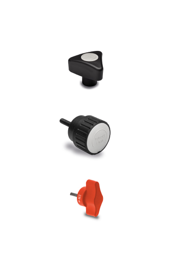
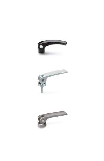
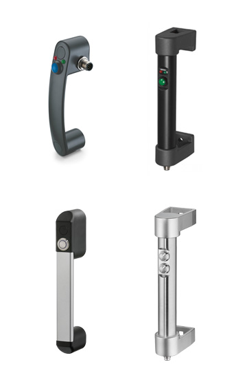
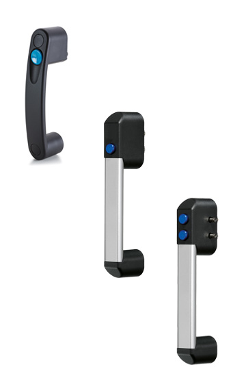
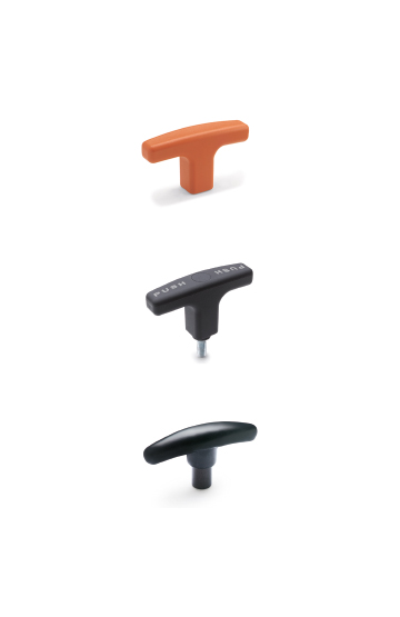
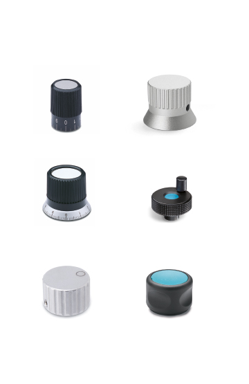
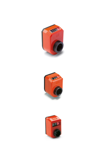
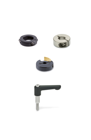
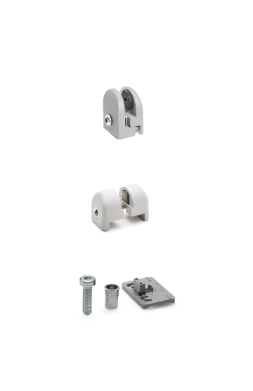
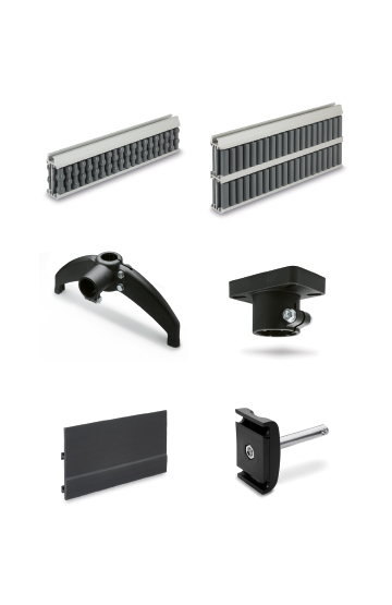
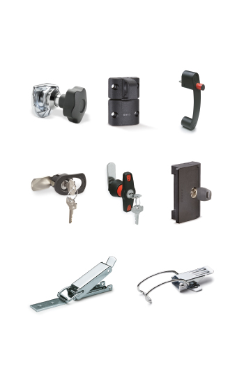
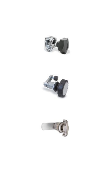
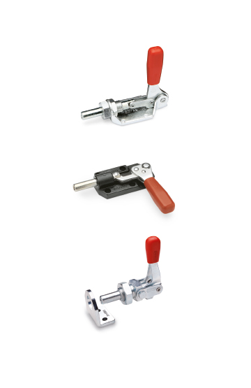
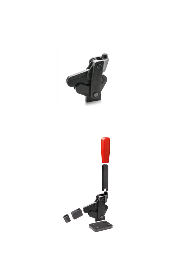
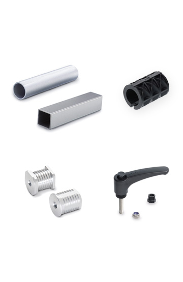
Clamping knobs, adjustable handles and self-locking pins for clamping operations in the field of photography, lighting and electronic equipment
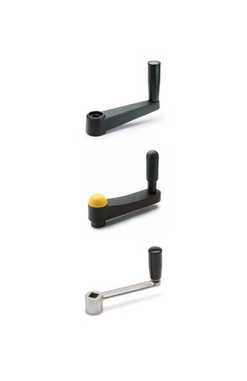
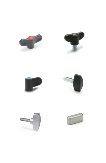
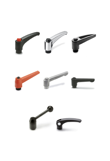
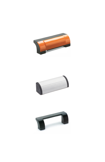
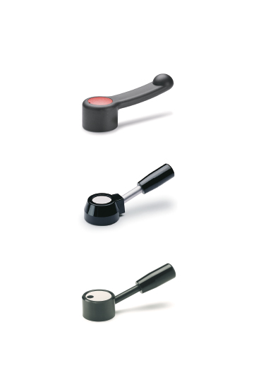
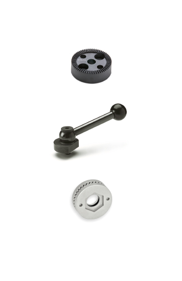
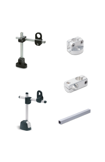
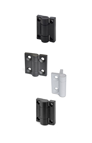
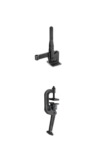
Components to perform clamping and locking operations on machinery or equipment. Ergonomics and design combined with colours
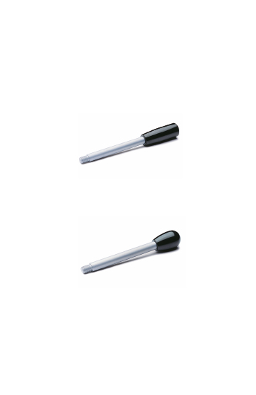
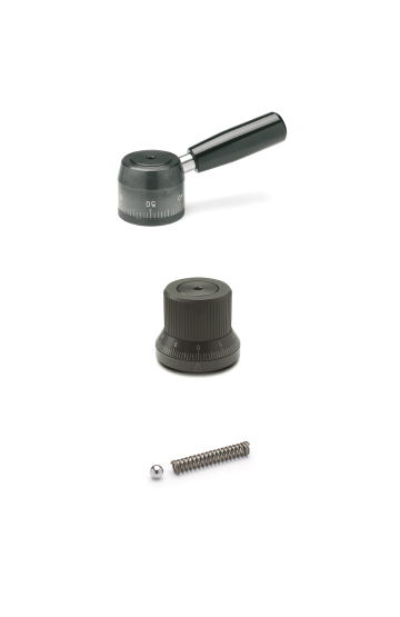
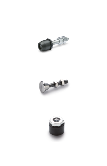
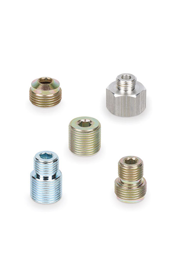
Brass.
Copper – Zinc Alloy (Cu-Zn Alloy), with coating in PTFE.
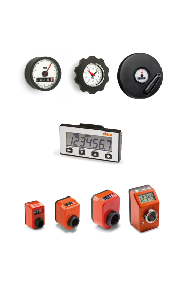
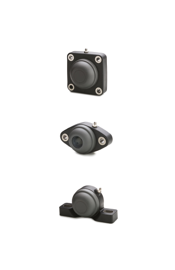
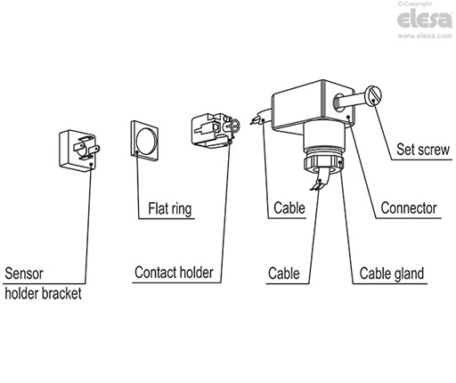
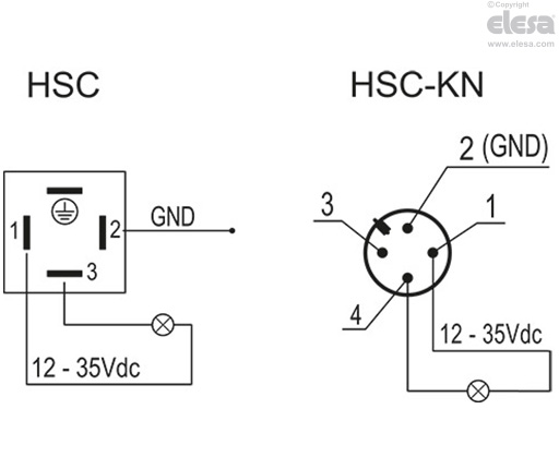
polyamide-based technopolymer (PA), black colour, with built-in cable gland and contact holder.
IP65 protection class, according to EN 60529 ).
Connector M12x1 - 4-pin with thread in polyamide-based (PA) technopolymer, black colour, matte finish.
IP 67 protection class.
For correct installation see Warnings
-30 / +125°C.
50 bar.
Suitable for the detection of conductive liquids such as water and non-conductive liquids such as oil/diesel.
The sensor activation delay, equal to 4 seconds, represents the time elapsed between the detection of the level inside the tank and the sending of the signal to the PLC.
The differential required for the calibration of the output signal hysteresis is calculated starting from the point of intervention (l1) and represents the virtual point of intervention obtained by adding the value of the differential to the value l1.
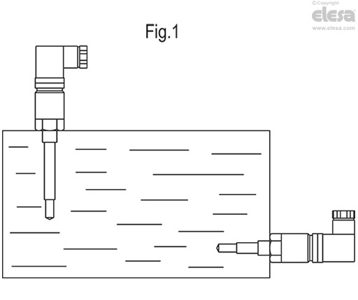
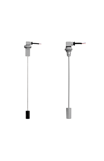
The sensor can be mounted both vertically and horizontally.
| Electrical features | |
| Description | Features |
| Power supply | 15 – 35 Vcc |
| Current drawn by the internal circuit | 5 mA |
| Electrical output | Push - Pull |
| Max load | 3W |
| Activation delay | 4 sec |
| Differential | 3 mm |
The level measurement is based on the variation of the electrical capacity inside the tank; the level probe and the metal wall create a sort of capacitor whose electrical capacity varies according to the quantity of liquid contained in the tank itself.
As the level inside the tank increases, the electrical capacity of the probe increases accordingly.
For example, an empty tank has a lower electrical capacity, while a full tank has a higher one.
The sensor can be mounted both vertically and horizontally (Fig.1).
It is advisable to periodically check the condition of the electrode and its coating and, if necessary, proceed with cleaning using non-corrosive liquids.
For both installation solutions, horizontal on the side of the tank or vertical, do not install the sensor on connecting tubes where vapours could condense or residues could remain which could affect the detection.