
SELF-SANITISATION AGAINST BACTERIA AND FUNGI
Close

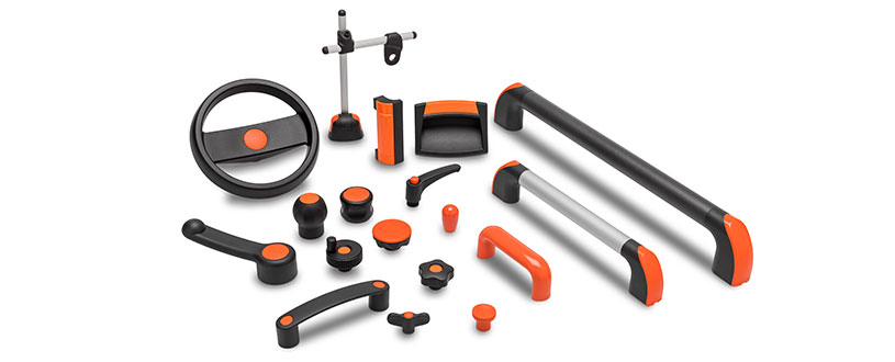
Components for manoeuvring, clamping and locking operations on equipment, including sports equipment and furniture in the nautical sector.
Corrosion resistance, ergonomics, compact shapes and great care in the choice of materials and finishes ease of cleaning
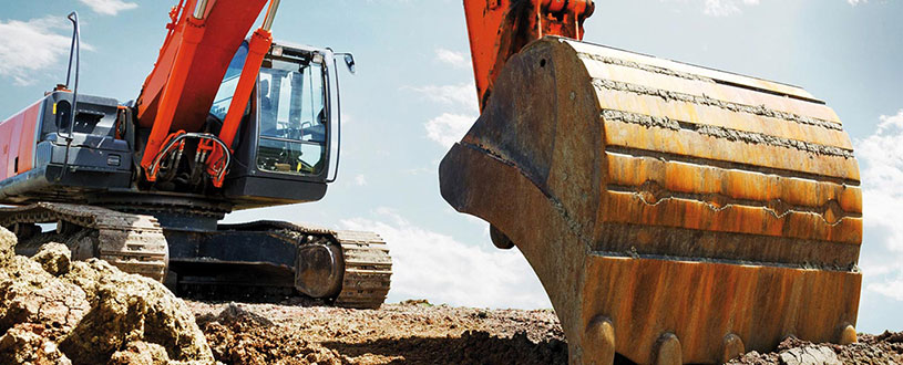
Components for construction vehicles, equipment and machinery which operate in particularly unfavourable conditions
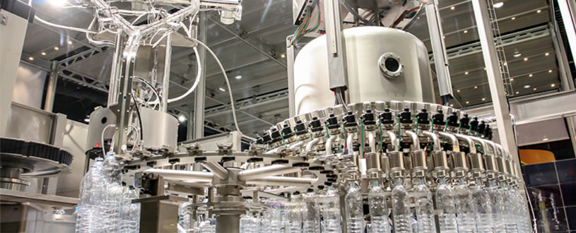
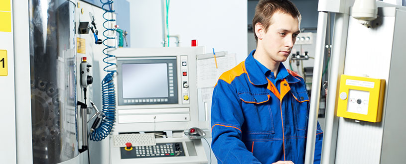
High quality standards, precision in tolerances and care in surface finishes are requirements that ensure greater precision in operation
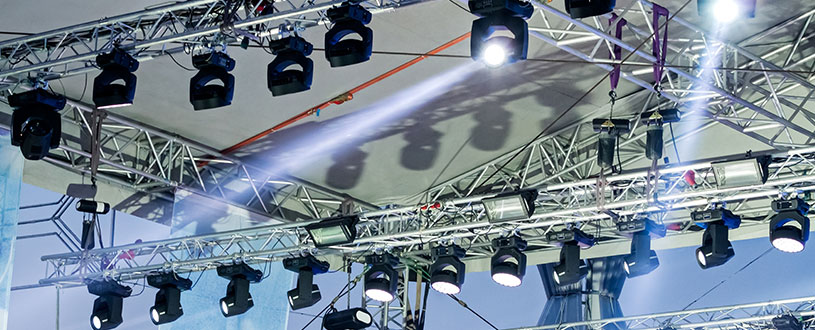
Clamping knobs, adjustable handles and self-locking pins for clamping operations in the field of photography, lighting and electronic equipment
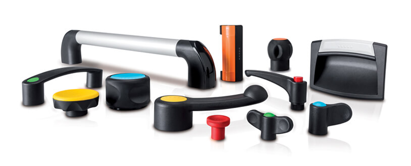
Components to perform clamping and locking operations on machinery or equipment. Ergonomics and design combined with colours

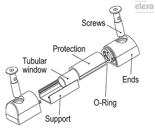
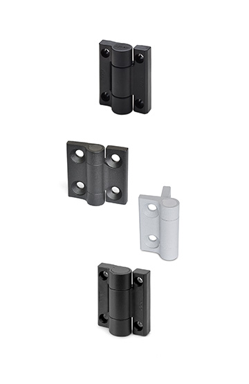
Glass-fibre reinforced polyamide based (PA) technopolymer, black colour.
Aluminium in natural colour.
White lacquered aluminium. It can be taken out before assembly to allow the insertion of level lines or words.
Technopolymer, black colour, with a built-in magnetic element to activate the electric contact when the float reaches the contact threshold located at about 55 mm above the axis of the lower screw (data referred to mineral oil type CB68, according to ISO 3498, temperature 23°C).
In polyamide based (PA) technopolymer. Essential in cases where the reservoir is made out of ferromagnetic material in order to prevent the interaction between the magnet and the metal mass of the reservoir.
Perfectly watertight, incorporating the relay (reed) with two output conductors (NO and NC version) and/or with MAX temperature sensor (80°C) and/or temperature probe.
For a correct assembly see Warnings.
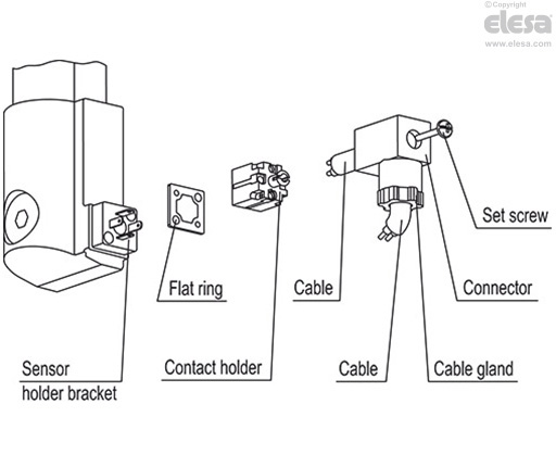
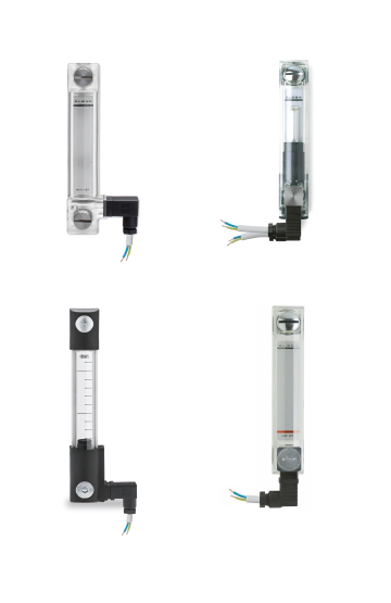
With built-in cable gland and contact holder. Front or axial output (high or low) ensuring protection against water sprays (protection class IP 65 according to table EN 60529).
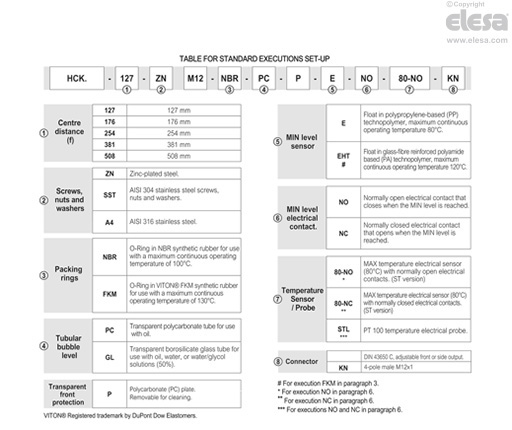
See configuration table.
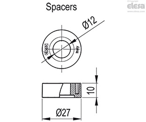
The HCK-E-S level indicator with lateral connector output allows the level of intervention of the sensor to be minimised.
In case of use of an extension with angled connector, the direction of the cable output is shown in Fig.1.
In laboratory tests carried out for a relatively limited time with the following liquids at a temperature of 23° C: mineral oil type CB68 (according to ISO 3498) for HCK, mineral oil type CB68 (according to ISO 3498) water or water/glycol-based solutions ( 50%) for HCK-GL, the resistance values were much higher than 35 bar.
For use with fluids other than mineral oils and under particular different pressure and temperature conditions, please contact ELESA Technical Department.
In any case we suggest to verify the suitability of the product under the actual working conditions.
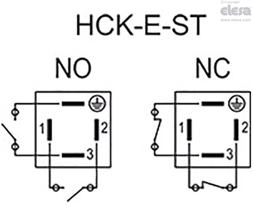
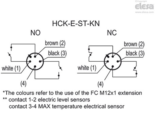
| HCK-E-ST - HCK-E-ST-KN | |
| Electrical features | MIN level sensor |
| Power supply | AC/DC |
| Electric contacts | NO normally open NC normally closed |
| Maximum applicable voltage | NO: 140 Vac, 200 Vdc NC: 140Vac, 150 Vdc |
| Maximum switching current | 1 A |
| Maximum current | NO: 1.2A NC: 2A |
| Maximum commutable power | NO: 10 Va NC: 20 Va |
| Cable gland (only HCK-E-ST) | Pg 7 (for cables in sheath with Ø 6 or 7 mm) |
| Conductors cross-section (only HCK-E-ST) | Max. 1.5 mm2 |
| Connector (only HCK-E-ST-KN) | M12x1 |
| Do not mount this indicator in proximity to magnetic fields. | |
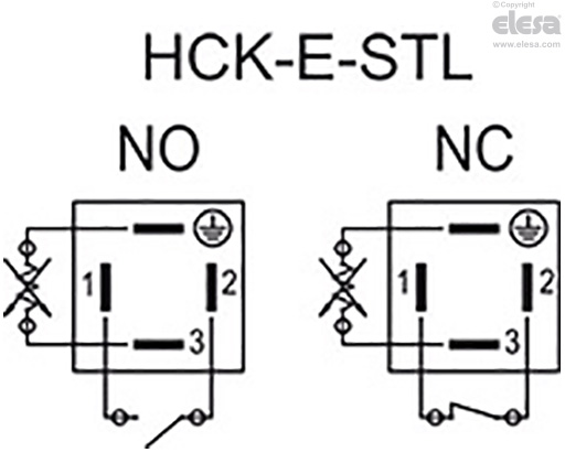
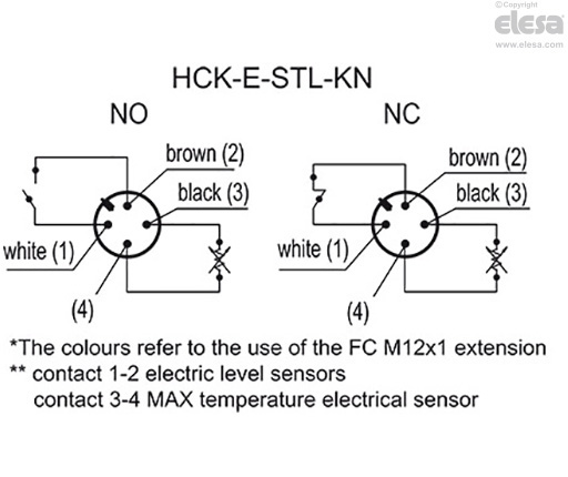
| HCK-E-STL - HCK-E-STL-KN | |
| Electrical features | MIN level sensor |
| Power supply | AC/DC |
| Electric contacts | NO normally open NC normally closed |
| Maximum applicable voltage | NO: 140 Vac, 200 Vdc NC: 140Vac, 150 Vdc |
| Maximum switching current | 1 A |
| Maximum current | NO: 1.2A NC: 2A |
| Maximum commutable power | NO: 10 Va NC: 20 Va |
| Cable gland (only HCK-E-STL) | Pg 7 (for cables in sheath with Ø 6 or 7 mm) |
| Conductors cross-section (only HCK-E-STL) | Max. 1.5 mm2 |
| Connector (only HCK-E-STL-KN) | M12x1 |
| Do not mount this indicator in proximity to magnetic fields. | |
| HCK-E-ST - HCK-E-ST-KN | ||
| Electrical features | MAX temperature sensor | |
| Power supply | AC/DC | |
| Electric contacts | NO normally open NC normally closed | |
Voltage / Maximum current | 250 Vac - 2 A | (resistive loads) |
| 115 Vac- 3A | ||
| 24 Vdc - 3 A | ||
| 12 Vdc - 4 A | ||
| Minimum current | 500 mA | |
| Cable gland (only HCK-E-ST) | Pg 7 (for cables in sheath with Ø 6 or 7 mm) | |
| Conductors cross-section (only HCK-E-ST) | Max. 1.5 mm2 | |
| Connector (only HCK-E-ST-KN) | M12x1 | |
| Do not mount this indicator in proximity to magnetic fields. | ||
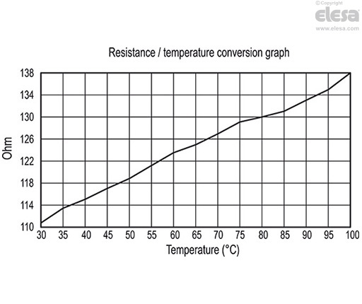
The working principle of the temperature probe is to measure the variation of resistance of a platinum element: 100 ohm = 0°C, 138.4 ohm = 100°C.
The function between temperature (T) and resistance (R) is approximately linear over a small temperature range: for example, if you assume that it is linear over the 0° to 100°C range, the error at 50°C is 0.4°C.
For precision measurement, it is necessary to linearise the resistance to give an accurate temperature. The most recent definition of the function between resistance and temperature is International Temperature Standard 90 (ITS-90). The function between resistance and temperature, obtained in laboratory tests, measuring directly the resistance value on the contacts is shown in the graph. We suggest, anyway, to set the system in order to compensate both heat dissipation and cable resistance.
The temperature variation of 1°C causes a 0.384 ohm variation in the probe resistance. Therefore, even a small error in the resistance measurement (for example, if the resistance of the cables connecting to the probe were not considered) translates into a significant error in the temperature measurement.
Because of the low signal levels, it is important to keep any cables away from electric cables, motors, switchgear and other devices that may emit magnetic or electrical noise. Using screened cable, with the screen grounded at one end, may help to reduce interference.
Furthermore, if long connection cables are used, make sure that the signal measurement and reception device is designed to compensate for the resistance of the cables themselves.
| HCK-E-STL - HCK-E-STL-KN | |
| Electrical features | Temperature probe |
| Power supply | AC/DC |
| Maximum current | 1mA |
| Cable gland (only HCK-E-STL) | Pg 7 (for cables in sheath with Ø 6 or 7 mm) |
| Conductors cross-section (only HCK-E-STL) | Max. 1.5 mm2 |
| Connector (only HCK-E-STL-KN) | M12x1 |
| Do not mount this indicator in proximity to magnetic fields. | |
FC-M12x1: extensions with 4 pole M12 female axial connector.